Mazda CX-5 Service & Repair Manual: Wheel Hub Component Removal/Installation [Awd]
CAUTION:
-
Performing the following procedures without first removing the ABS wheel-speed sensor may possibly cause an open circuit in the wiring harness if it is pulled by mistake. Before performing the following procedures, disconnect the ABS wheel-speed sensor connector (body side) and fix the wiring harness to an appropriate place where it will not be pulled by mistake while servicing the vehicle.
1. When working on the left side of the vehicle, disconnect the auto leveling sensor link. .
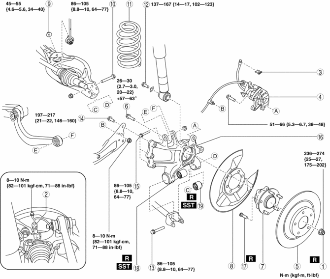
2. Remove in the order indicated in the table.
3. Install in the reverse order of removal.
4. Inspect the rear wheel alignment..
|
1 |
Locknut (See Locknut Installation Note.) |
|
2 |
ABS wheel-speed sensor |
|
3 |
Brake hose clip |
|
4 |
Brake caliper component |
|
5 |
Disc plate |
|
6 |
Bolt (wheel hub) (See WHEEL HUB COMPONENT REMOVAL/INSTALLATION [2WD].) |
|
7 |
Wheel hub |
|
8 |
Dust cover |
|
9 |
Rear stabilizer control link lower side nut |
|
10 |
Rear lower arm outer bolt (See WHEEL HUB COMPONENT REMOVAL/INSTALLATION [2WD].) |
|
11 |
Rear coil spring (See REAR COIL SPRING REMOVAL/INSTALLATION.) |
|
12 |
Rear shock absorber lower bolt (See REAR SHOCK ABSORBER REMOVAL/INSTALLATION.) |
|
13 |
Rear lateral link outer bolt (See REAR LATERAL LINK REMOVAL/INSTALLATION.) |
|
14 |
Rear trailing link installation bolt (See REAR LATERAL LINK REMOVAL/INSTALLATION.) |
|
15 |
Bolt (rear upper arm outer side) |
|
16 |
Hub support |
|
17 |
Wheel hub bolt (See WHEEL HUB COMPONENT REMOVAL/INSTALLATION [2WD].) |
|
18 |
Hub support bushing (front) (See WHEEL HUB COMPONENT REMOVAL/INSTALLATION [2WD].) |
|
19 |
Hub support bushing (rear) (See WHEEL HUB COMPONENT REMOVAL/INSTALLATION [2WD].) |
Locknut Installation Note
1. After tightening the locknut once at a torque of 390 N·m {40 kgf·m, 288 ft·lbf}
, return it temporarily 180 degrees
, then retighten it to a torque of 236—274 N·m {25—27 kgf·m, 175—202 ft·lbf}
.
 Turbine/Input Shaft Speed Sensor, Output Shaft Speed Sensor [Fw6 A EL, Fw6 Ax
EL]
Turbine/Input Shaft Speed Sensor, Output Shaft Speed Sensor [Fw6 A EL, Fw6 Ax
EL]
Purpose/Function
The turbine/input shaft speed sensor detects the rotation speed of the input
shaft (low clutch drum).
The output shaft speed sensor detects the rotation speed of the ...
 Differentials
...
Other materials:
Controller Area Network (Can)
Outline
The DSC HU/CM sends and receives data to and from other modules via the CAN
system. Refer to MULTIPLEX COMMUNICATION SYSTEM for a detailed explanation of
the CAN system..
Data sent
Cruise control system-related information
DSC system-related information
...
Starter Interlock Switch Removal/Installation [C66 M R]
1. Disconnect the negative battery cable..
2. Disconnect the starter interlock switch connector.
3. Remove the starter interlock using the following procedure:
a. Detach hook A in the direction of the arrow shown in the figure.
b. Slide the starter interlock switch in the direction of th ...
Fuel Shut Off Valve
U.S.A. And CANADA
Purpose, function
Prevents fuel from flowing to the charcoal canister during tight turns or
vehicle rollover.
Releases evaporative gas to the charcoal canister.
While refueling, the fuel shut-off valve closes to prevent a fuel overflow.
Construction ...
