Mazda CX-5 Service & Repair Manual: Rear Bumper Removal/Installation
CAUTION:
-
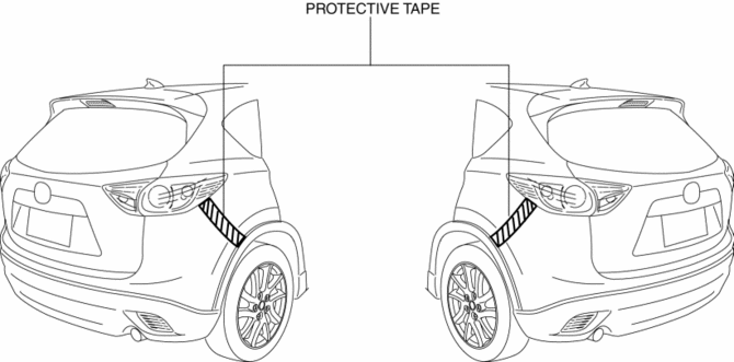
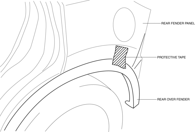
Affix the protective tape to the position (body side) shown in the figure.
1. Disconnect the negative battery cable..
2. Remove the rear combination light..
3. Remove fasteners A.
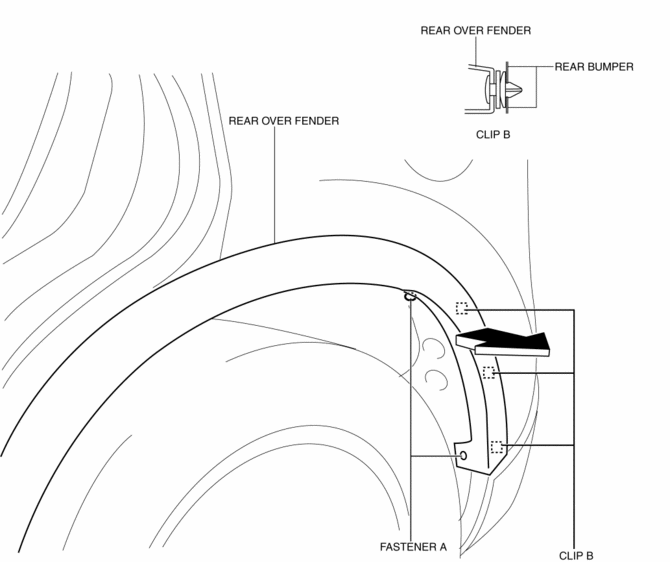
4. Pull the rear over fender in the direction of the arrow shown in the figure above, then peel it back while removing clips B.
CAUTION:
-
After removing clips B, insert a rag between the rear fender panel and the rear over fender to prevent the rear fender panel and clips B from being damaged.
5. Remove the rear splash shield..
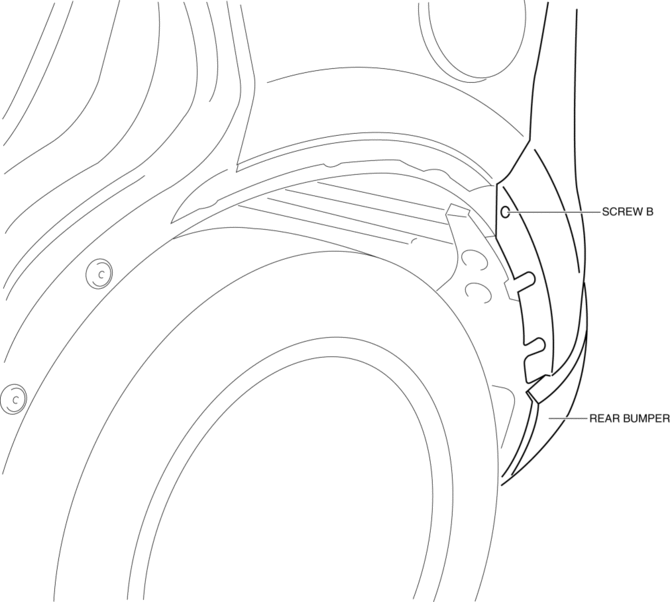
6. Remove screw B.
7. Remove screws C.
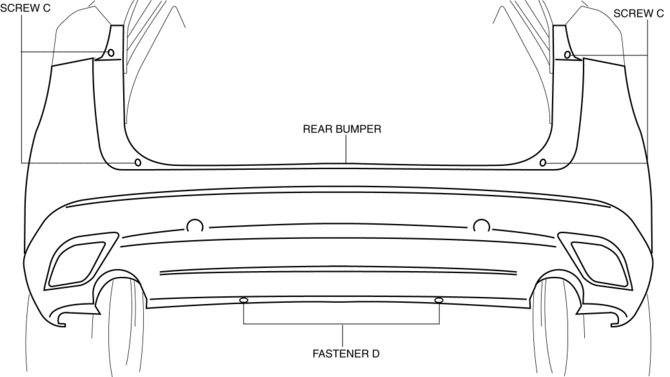
8. Remove fasteners D.
9. Pull the end of the rear bumper (A) in the direction of the arrow (1) shown in the figure, while removing tabs.
CAUTION:
-
The rear bumper and rear bumper slider are engaged firmly. If they are disengaged forcibly the bumper could fall and be damaged. Perform the servicing carefully when disengaging the rear bumper from the rear bumper slider.
-
When disengaging the rear bumper from the rear bumper slider, the rear bumper could fall and be damaged. Support the front bumper so that it does not fall.
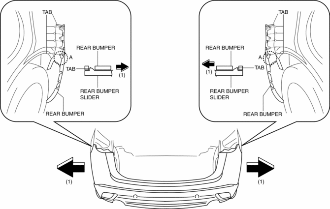
10. Remove the rear bumper from rear bumper slider.
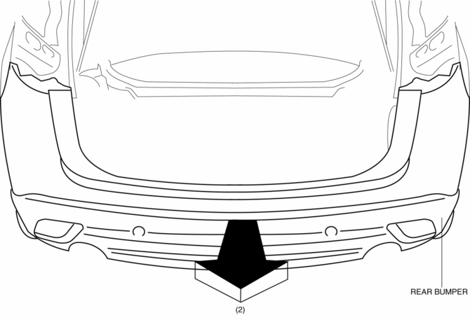
11. Remove the rear bumper in the direction of the arrow (2) shown in the figure.
CAUTION:
-
After removing rear bumper, it may hit the rear over fender and cause a damage and/or injury. Perform the following procedure to prevent the rear over fender from being damaged.
-
Fix the rear over fender and rear fender panel with protective tape.
12. Install in the reverse order of removal.
 Rear Bumper Reinforcement Removal/Installation
1. Disconnect the negative battery cable..
2. Remove the following parts:
a. Rear splash shield.
b. Rear combination light.
c. Rear bumper.
3. Remove the hanger rubber in the direction of th ...
 Rear End Panel Installation [Panel Replacement]
Symbol Mark
Installation Procedure
1. When installing new parts, measure and adjust the body as necessary to conform
with standard dimensions.
2. Drill holes for the plug welding before inst ...
Other materials:
Hazardous Driving
WARNING
Be extremely careful if it is necessary to downshift on slippery surfaces: Downshifting
into lower gear while driving on slippery surfaces is dangerous. The sudden change
in tire speed could cause the tires to skid.
This could lead to loss of vehicle control and an accident.
When driv ...
Relay And Fuse Block Disassembly/Assembly
1. Insert a tape-wrapped flathead screwdriver into the service hole in the position
shown in the figure.
2. Move the flathead screwdriver in the direction of the arrow (1) shown in the
figure, pull up relay and fuse block No.1 in the direction of the arrow (2) shown
in the figure, and de ...
Front Fog Light Removal/Installation
1. Disconnect the negative battery cable..
2. Remove the screws and bolt.
3. Pull up the front under cover No.1 and remove the mudguard screw shown in
the figure.
4. Disconnect the connector.
5. While pressing the clip tab in the direction of the arrow (1) shown in the
figure ...
