Mazda CX-5 Service & Repair Manual: Side Air Bag Sensor Removal/Installation [Two Step Deployment Control System]
WARNING:
-
Handling the side air bag sensor improperly can accidentally operate (deploy) the air bag module, which may seriously injure you. Read the air bag system service warnings and cautions before handling the side air bag sensor..
1. Switch the ignition to off.
2. Disconnect the negative battery cable and wait for 1 min or more
..
3. Remove the following parts:
a. Remove the trunk board..
b. Remove the trunk end trim..
c. Remove the rear scuff plate..
d. Remove the trunk side trim..
4. Remove the bolt.
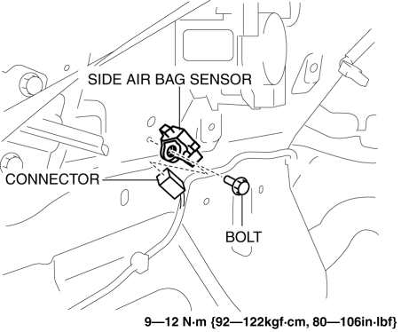
5. Disconnect the connector..
6. Remove the side air bag sensor.
7. Install in the reverse order of removal.
8. Switch the ignition ON (engine off or on).
9. Verify that the air bag system warning light illuminates for approx. 6 s
and goes out.
-
If the air bag system warning light does not operate normally, refer to the on-board diagnostic system (air bag system) and perform inspection of the system..
Connector Disconnect Note
1. Press the area (1) indicated by the arrow and slide it as shown in the figure (2).
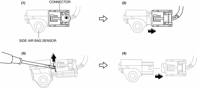
2. Lift up the location shown in the figure using a tape-wrapped flathead screwdriver (3) and disconnect the connector (4).
 Side Air Bag Sensor No. 1 Removal/Installation [Standard Deployment Control
System]
Side Air Bag Sensor No. 1 Removal/Installation [Standard Deployment Control
System]
WARNING:
Handling the side air bag sensor improperly can accidentally operate (deploy)
the air bag module, which may seriously injure you. Read the air bag system
service warnings and ca ...
 Side Air Bag Sensor [Standard Deployment Control System]
Purpose
The side air bag sensor detects an impact during a lateral collision.
Function
The side air bag sensor converts the detected impact to an electrical signal.
Construct ...
Other materials:
Wiper And Washer Switch Removal/Installation
1. Switch the ignition ON (engine off or on).
2. Open the driver's door.
3. Switch the ignition OFF.
4. Disconnect the negative battery cable..
5. Remove the column cover..
6. Rotate the steering wheel in the direction of the arrow shown in the figure
to the angle where the service h ...
Climate Control Unit Inspection [Full Auto Air Conditioner]
1. Remove the climate control unit with the connector connected..
2. Switch the ignition ON (engine off or on).
3. Connect the negative (-) lead of the tester to body ground.
4. By inserting the positive (+) lead of the tester into each climate control
unit terminal, measure the voltage acco ...
Low Fuel Warning Light
Purpose
The low fuel warning light warns the driver that the remaining fuel level
is low.
Function
The instrument cluster calculates the fuel quantity based on the following
CAN signals, and if a remaining fuel amount of approx. 10 L {2.6 US gal, 2.2
Imp gal} (fuel gauge ...
