Mazda CX-5 Service & Repair Manual: Rear Accessory Socket Inspection
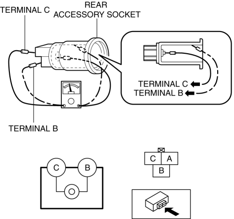
1. Remove the rear accessory socket..
2. Connect the tester probe to the position shown in the figure and verify that there is continuity.

-
If it cannot be verified, replace the rear accessory socket..
 Front Accessory Socket Removal/Installation
1. Disconnect the negative battery cable..
2. Remove the front console..
3. Insert a tape-wrapped flathead screwdriver into the gap between the cap tab
and socket.
4. Move the flathead scr ...
 Rear Accessory Socket Removal/Installation
1. Disconnect the negative battery cable..
2. Insert a tape-wrapped flathead screwdriver into the service hole in the position
shown in the figure.
3. Move the flathead screwdriver in the di ...
Other materials:
Sunroof Switch Inspection
1. Disconnect the negative battery cable..
2. Remove the front map light..
3. Verify that the continuity between the sunroof switch terminals is as indicated
in the table.
If not as indicated in the table, replace the sunroof switch.
...
Air Bag System Service Warnings [Two Step Deployment Control System]
Air Bag Module Inspection
Inspecting an air bag module using a tester can operate (deploy) the air
bag module, which may cause serious injury. Do not use a tester to inspect an
air bag module. Always use the on-board diagnostic function to diagnose the
air bag module for malfunctions ...
Power Seat Switch Removal/Installation
WARNING:
Handling a side air bag improperly can accidentally operate (deploy) the
air bag, which may seriously injure you. Read the service warnings/cautions
in the Workshop Manual before handling the front seat (side air bag integrated)..
1. Switch the ignition off (LOCK).
2. ...
