
Mazda CX-5 Service & Repair Manual: Rear Accessory Socket Removal/Installation
1. Disconnect the negative battery cable..
2. Insert a tape-wrapped flathead screwdriver into the service hole in the position shown in the figure.
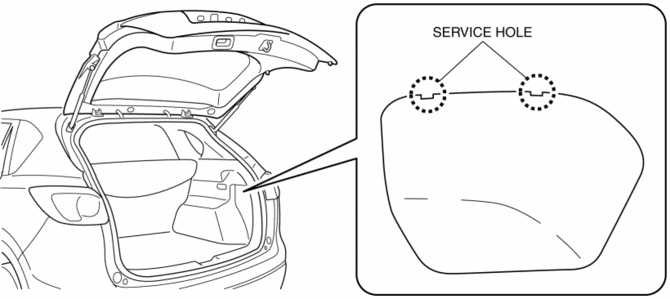
3. Move the flathead screwdriver in the direction of the arrow (1) shown in the figure, pull out the service hole cover, and detach the service hole cover tab and trunk side trim.
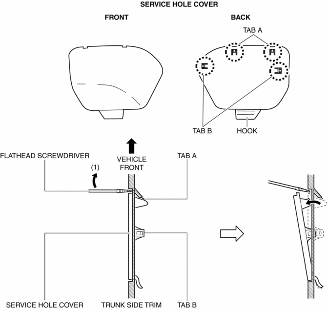
4. Pull out the service hole cover in the direction of the arrow (2) shown in the figure and pull out the service hole cover hook from the trunk side trim.
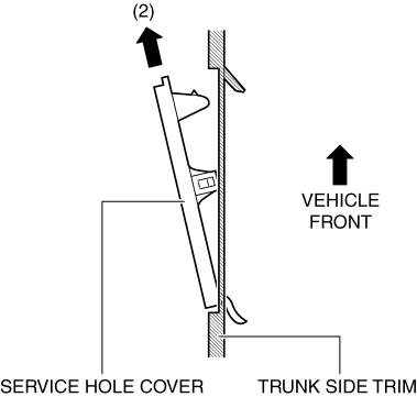
5. Remove the service hole cover.
6. Disconnect the connector.
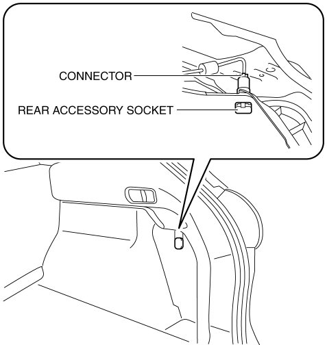
7. Insert a tape-wrapped flathead screwdriver into the service hole in the position shown in the figure.
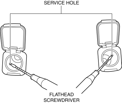
8. While pressing the cap tab in the direction of arrow (3) shown in the figure, push out the rear accessory socket in the direction of arrow (4) to detach the cap tab from the socket.
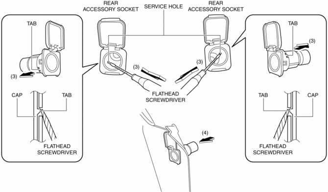
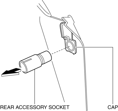
9. Pull the rear accessory socket in the direction of the arrow shown in the figure and remove it.
10. While pressing the cap tab in the direction of the arrow (5) shown in the figure, push out the cap in the direction of the arrow (6) shown in the figure to detach the cap tab from the trunk side trim.
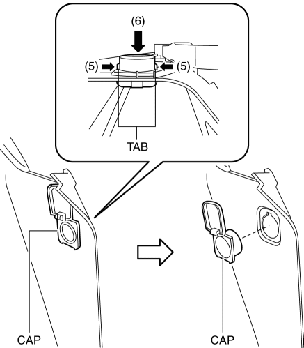
11. Remove the cap.
12. Install in the reverse order of removal.
 Rear Accessory Socket Inspection
1. Remove the rear accessory socket..
2. Connect the tester probe to the position shown in the figure and verify that
there is continuity.
If it cannot be verified, replace the rear ac ...
 Safety Systems
...
Other materials:
Liftgate Garnish Removal/Installation
1. Disconnect the negative battery cable..
2. Remove the following parts:
a. Liftgate upper trim.
b. Liftgate side trim.
c. Liftgate recess.
d. Liftgate lower trim.
3. Disconnect the connectors.
4. Remove nuts A.
5. Detach clips B shown in the figure.
6. Remove the liftgate ...
Front Wiring Harness Protector Removal/Installation
Front Wiring Harness Protector No.1
1. Disconnect the negative battery cable..
2. Remove the air cleaner case..
3. While pressing the tabs of clip A in the direction of the arrows (1) shown
in the figure, pull clip A in the direction of the arrow (2) shown in the figure
to detach the tab of ...
Battery Inspection [Skyactiv G 2.0]
WARNING:
Since battery acid is toxic, be careful when handling the battery.
Since battery acid is highly corrosive, be careful not to allow it to contact
clothing or the vehicle.
In case battery acid contacts skin, eyes, or clothing, flush it immediately
with running wa ...
