Mazda CX-5 Service & Repair Manual: Oil Seal (Differential) Replacement [Fw6 A EL, Fw6 Ax EL]
Transaxle Case Side
1. Remove the front under cover No.2..
2. Drain the ATF..
3. Disconnect the drive shaft (LH) from the transaxle..
CAUTION:
-
The oil seal is easily damaged by the sharp edges of the drive shaft splines. Do not let the splines contact the oil seal.
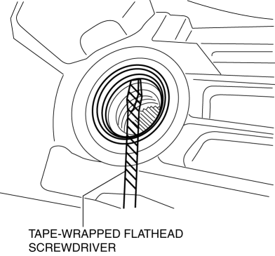
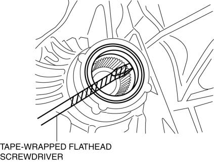
4. Remove the oil seal using a tape-wrapped flathead screwdriver.
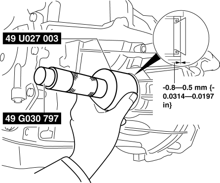
5. Using the SSTs
and a hammer, tap a new oil seal in evenly until the SST
(49 U027 003) contacts the transaxle case.
6. Coat the lip of the oil seal with ATF.
7. Install the drive shaft (LH) to the transaxle..
8. Add the ATF..
9. Install the front under cover No.2..
10. Perform the “Mechanical System Test”..
Converter housing Side (FW6A-EL)
1. Remove the front under cover No.2..
2. Drain the ATF..
3. Disconnect the drive shaft (RH)..
CAUTION:
-
The oil seal is easily damaged by the sharp edges of the drive shaft splines. Do not let the splines contact the oil seal.
4. Remove the oil seal using a tape-wrapped flathead screwdriver.
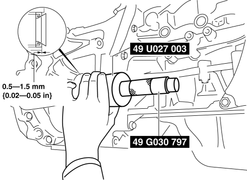
5. Using the SSTs
and a hammer, tap a new oil seal in evenly until the SST
(49 U027 003) contacts the transaxle case.

6. Coat the lip of the oil seal with ATF.
7. Install the drive shaft (RH)..
8. Add the ATF..
9. Install the front under cover No.2..
10. Perform the “Mechanical System Test”..
Converter housing Side (FW6AX-EL)
1. Remove the front under cover No.2..
2. Drain the ATF..
3. Remove the transfer..
CAUTION:
-
The oil seal is easily damaged by the sharp edges of the drive shaft splines. Do not let the splines contact the oil seal.
4. Remove the oil seal using a tape-wrapped flathead screwdriver.
5. Using the SSTs
and a hammer, tap a new oil seal in evenly until the SST
(49 U027 003) contacts the transaxle case.
6. Coat the lip of the oil seal with ATF.
7. Install the transfer..
8. Add the ATF..
9. Install the front under cover No.2..
10. Perform the “Mechanical System Test”..
 Oil Seal (Differential) Replacement [C66 M R]
1. Remove the front under cover No.2..
2. Drain the manual transaxle oil..
3. Disconnect the drive shaft (LH) from the MTX..
4. Disconnect the drive shaft (RH) from the MTX..
5. Remove the oil ...
 Oil Seal (Side Gear) Replacement
1. Remove the drain plug and the drain differential oil into a container.
2. Install a new washer and the drain plug, and tighten.
3. Remove the rear drive shaft..
4. Remove the clip from the dr ...
Other materials:
Steering Wheel
Steering Wheel
WARNING
Never adjust the steering wheel while the vehicle is moving: Adjusting the steering
wheel while the vehicle is moving is dangerous.
Moving it can very easily cause the driver to abruptly turn to the left or right.
This can lead to loss of control or an accident.
Steeri ...
Washer Nozzle
Purpose
The washer nozzle sprays the washer fluid sent from the washer motor to the
optimum positions on the windshield.
Construction
A ball-shaped spray orifice is set inside the washer nozzle which can be
adjusted up or down.
The washer nozzle is moved u ...
Electric Variable Valve Timing Motor/Driver Inspection
WARNING:
A hot engine can cause severe burns. Turn off the engine and wait until it
is cool before servicing.
CAUTION:
Do not disassemble the electric variable valve timing motor/driver because
it is a precision unit.
Do not apply excessive force when rotating the ...
