Mazda CX-5 Service & Repair Manual: Engine Mount
Purpose, Function
-
The engine mount secures the engine and transaxle to the vehicle body, reducing vibration and noise.
Construction
-
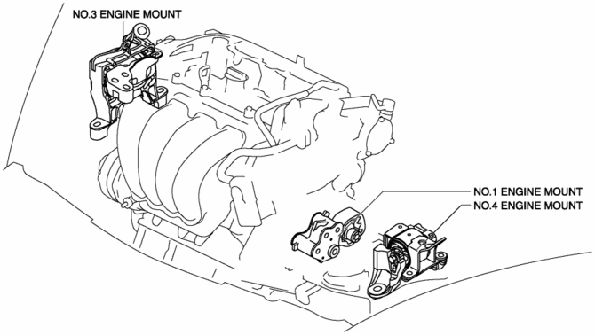
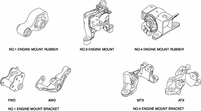
The three points at the engine front (No.3 engine mount), one side of the transaxle (No.1 engine mount), and the rear upper part of the transaxle (No.4 engine mount) are supported.
-
With the adoption of the oil-filled bushing type for the No.3 engine mount and No.4 engine mount rubber, the damper effect has been improved.
Operation
-
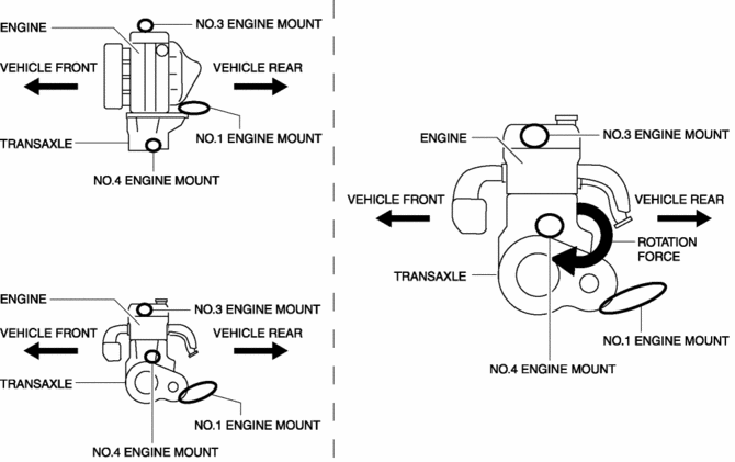
By locating the one side of the transaxle (No.1 engine mount) to the transaxle lower end, the No.1 engine mount absorbs the rotation force to the powertrain generated during engine torque fluctuation. The layout is designed to disperse the rotation force to the front/back directions of the engine.
 Engine Mount Disassembly/Assembly
No.1 Engine Mount (2WD)
1. Remove the front under cover No.2..
2. Remove in the order indicated in the table.
3. Install in the reverse order of removal.
1
No.1 engi ...
 Piston Assembly
...
Other materials:
Oil Strainer
Purpose, Function
The oil strainer suctions the engine oil in the oil pan using the oil pump
vacuum. The engine oil is filtered by the internal filter at that time.
Construction
The oil strainer is installed on the suction port of the oil pump.
The oil strain ...
Theft Deterrent Horn Inspection
1. Disconnect the negative battery cable..
2. Remove the following parts:
a. Trunk end trim.
b. Rear scuff plate (RH).
c. Trunk side trim (RH).
d. Theft-deterrent horn.
3. Apply battery positive voltage to horn terminal A, and connect the horn retaining
bolt to ground as shown in the f ...
DRL (Daytime Running Light) System
Outline
The DRL system automatically switches the headlights to HI beams (50% dim)
or illuminates the DRL bulb when the ignition is switched ON (engine on), the
parking brake is released, and the shift lever is in a position other than P
(ATX).
The front body control module ( ...
