Mazda CX-5 Service & Repair Manual: Center Pillar Installation [Panel Replacement]
Symbol Mark

Installation Procedure
1. When installing new parts, measure and adjust the body as necessary to conform with standard dimensions.
2. Drill holes for the plug welding before installing the new parts.
3. After temporarily installing new parts, make sure the related parts fit properly.
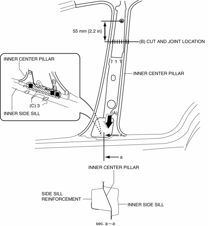
4. Insert the end of the inner center pillar locations indicated by (A) shown in the figure, between the inner side sill and side sill reinforcement.
5. Cut and join the area locations indicated by (B) shown in the figure.
6. Plug weld the 3 locations indicated by (C) shown in the figure.

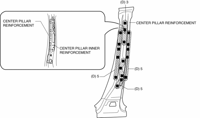
7. Plug weld the 18 locations indicated by (D) shown in the figure, then install the center pillar inner reinforcement to the center pillar reinforcement.

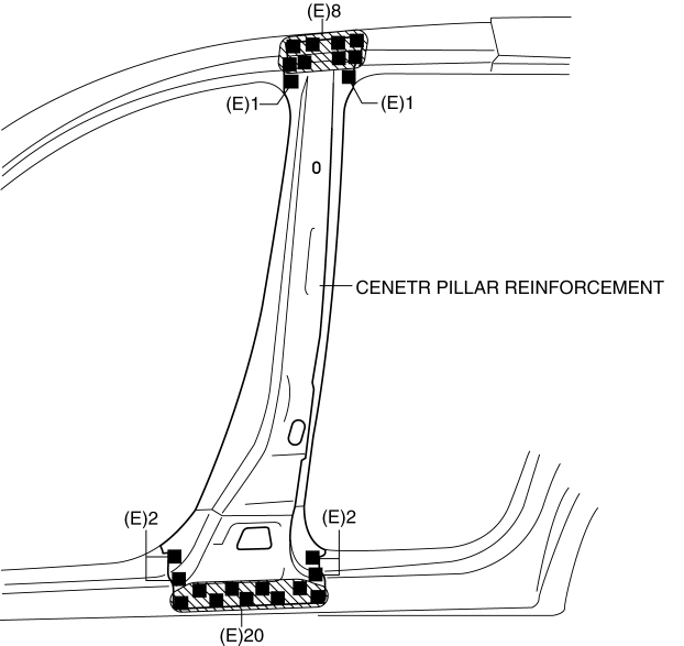
8. Plug weld the 34 locations indicated by (E) shown in the figure, then install the center pillar reinforcement.

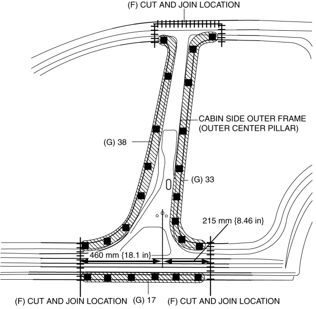
9. Cut and join the area locations indicated by (F) shown in the figure.
10. Plug weld the 88 locations indicated by (G) shown in the figure, then install the cabin side outer frame (outer center pillar).

 Cabin Side Frame Straight Line Dimensions [Dimensions]
Point symbol
Designation
Hole diameter or bolt or nut size mm {in}
A
Front side frame outer datum hole
?12 { ...
 Center Pillar Removal [Panel Replacement]
Symbol Mark
Removal Procedure
CAUTION:
Remove the curtain air bag module to prevent damage before servicing.
Front-side
Rear-side
CAUTION:
Avoid cutting with a bl ...
Other materials:
Oil Seal (Coupling Component) Replacement
1. Drain the differential oil into a container.
2. Remove the coupling component..
3. Remove the oil seal from the differential carrier using a screwdriver or similar
tool.
4. Apply differential oil to the new oil seal lip.
5. Install the new oil seal to the differential carrier using the ...
Thermostat
Purpose, Function
When the engine coolant temperature is low, the thermostat blocks the engine
coolant passage between the radiator and engine. As a result, because engine
coolant cycles without passing through the radiator, warming is promoted.
Construction
The thermostat ...
Car Navigation System
Outline
The car-navigation system displays point-of-origin and road guidance maps
via the audio unit display and provides guidance and information to the desired
point of destination.
NOTE:
For the car-navigation system operation, refer to the owner's manual.
...
