
Mazda CX-5 Service & Repair Manual: Cabin Side Frame Straight Line Dimensions [Dimensions]
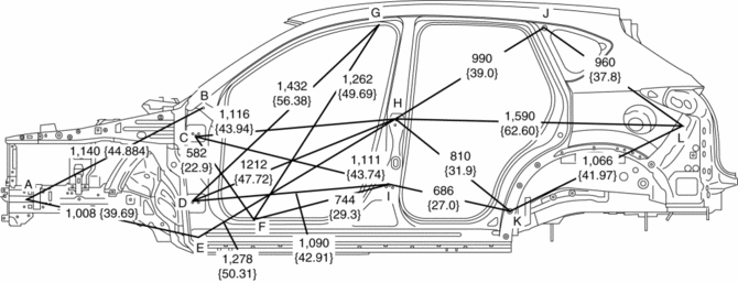
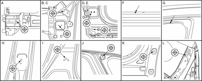
|
Point symbol |
Designation |
Hole diameter or bolt or nut size mm {in} |
|
A |
Front side frame outer datum hole |
?12 {0.47} |
|
B |
Front fender panel installation hole |
?10 {0.39} |
|
C |
Front door hinge installation hole |
?12 {0.47} |
|
D |
Front door hinge installation hole |
?12 {0.47} |
|
E |
Front fender panel installation hole |
?11 {0.43} |
|
F |
Cabin side frame (outer) notch |
- |
|
G |
Cabin side frame (outer) notch |
- |
|
H |
Rear door hinge installation hole |
?12 {0.47} |
|
I |
Rear door hinge installation hole |
?12 {0.47} |
|
J |
Quarter window glass installation hole |
?8 {0.3} |
|
K |
Rear over fender installation hole |
?10 {0.39} |
|
L |
Rear bumper slider installation hole |
?16 {0.63} |
 Body Sealing [Water Proof And Rust Preventive]
Sealant is applied to the parts where the panels meet and to the hemmed parts
of the door panel and hood panel to provide water proofing and rust proofing.
...
 Center Pillar Installation [Panel Replacement]
Symbol Mark
Installation Procedure
1. When installing new parts, measure and adjust the body as necessary to conform
with standard dimensions.
2. Drill holes for the plug welding before inst ...
Other materials:
Electric Variable Valve Timing Motor/Driver Removal/Installation
WARNING:
A hot engine can cause severe burns. Turn off the engine and wait until it
is cool before servicing.
CAUTION:
Applying excessive force (force of 100 N {10.2 kgf, 22.5 lbf} or more) to
the electric variable valve timing motor/driver may cause a malfunction. When
...
Headlight High Beam Indicator Light
Purpose
Notifies the user that the headlights (HI) are illuminated.
Function
Illuminates when the headlight (HI) or parking illumination conditions are
met.
Construction
Displayed in the instrument cluster.
Operation
1. When the light switch is operat ...
Intake Manifold
Purpose, Function
Distributes intake air to each cylinder evenly.
Optimizes the combustion efficiency and performance of the engine by distributing
intake air to each cylinder.
Construction
The intake manifold is installed to the cylinder head.
...
