Mazda CX-5 Service & Repair Manual: Wheel Apron Component Installation [Panel Replacement]
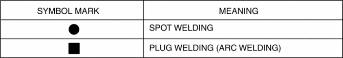
Symbol Mark
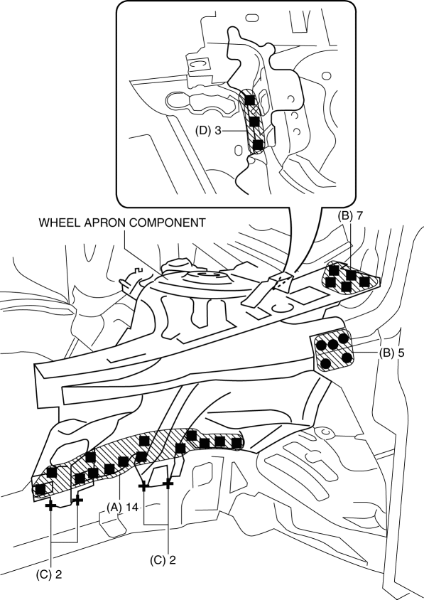
Installation Procedure
1. When installing new parts, measure and adjust the body as necessary to conform with standard dimensions.
2. Drill holes for the plug welding before installing the new parts.
3. After temporarily installing new parts, make sure the related parts fit properly.
4. Plug weld the 14 locations indicated by (A) from the front wheel housing side shown in the figure.
5. Spot weld the 5 locations indicated by (B) shown in the figure.
6. Arc weld the 4 locations indicated by (C) shown in the figure.
7. Plug weld the 3 locations indicated by (D) shown in the figure.
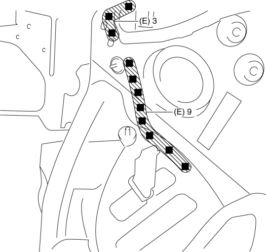
8. Plug weld the 12 locations indicated by (E) from the inside shown in the figure, then install the wheel apron component.
 Wheel Alignment Pre Inspection
1. Park the vehicle on level ground, in an unloaded condition*, with the wheels
straight forward.
*: Unloaded condition.....Fuel tank is full. Engine coolant and engine oil are
at specified leve ...
 Wheel Apron Component Removal [Panel Replacement]
Symbol Mark
Removal Procedure
1. Drill the 14 locations indicated by (A) from the front wheel housing side
shown in the figure.
2. Drill the 11 locations indicated by (B) shown in the figure ...
Other materials:
Canister Vent (Cv) Solenoid Valve Inspection
U.S.A. And CANADA
Airflow inspection
1. Disconnect the negative battery cable..
2. Remove the CV solenoid valve..
3. Inspect airflow between the ports under the following conditions.
Measured condition
Continuity between A—B
When volta ...
Rear Door Speaker Removal/Installation
Without Bose®
NOTE:
If the procedure is performed while holding the front door speaker cone,
it could deform the cone causing a malfunction. Therefore, perform the procedure
while holding any part other than the cone.
1. Disconnect the negative battery cable..
2. Remove the r ...
Passenger Sensing System [Two Step Deployment Control System]
Purpose
The passenger sensing system detects whether or not there is an occupant
on the passenger seat to control the operation (deployment) of the passenger-side
air bag system corresponding to the detected condition.
Function
Measures the total seated weight on the passen ...
