Mazda CX-5 Service & Repair Manual: Wheel Alignment Pre Inspection
1. Park the vehicle on level ground, in an unloaded condition*, with the wheels straight forward.
*: Unloaded condition.....Fuel tank is full. Engine coolant and engine oil are at specified level. Spare tire, jack and tools are in designated position.
2. Inspect the tire pressure.
-
Adjust to the recommended pressure if necessary..
3. Inspect the wheel bearing play.
-
Correct if necessary..
4. Inspect the wheel runout.
-
Correct if necessary..
5. Rock the vehicle, and verify that there is no looseness in the steering wheel joint and suspension ball joint.
6. Rock the vehicle, and verify that the shock absorber operates properly.
7. Measure height H from the center of the wheel to the fender brim.
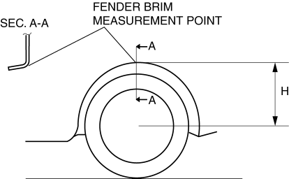
8. Verify that the difference between the left and right dimension H is within the specification.
-
If it exceeds the specification, repeat the Step 2—7.
-
Standard specification
-
10 mm {0.39 in} or less
 Wheels, Tires
...
 Wheel Apron Component Installation [Panel Replacement]
Symbol Mark
Installation Procedure
1. When installing new parts, measure and adjust the body as necessary to conform
with standard dimensions.
2. Drill holes for the plug welding before inst ...
Other materials:
Immobilizer System
The immobilizer system allows the engine to start only with a key the system
recognizes.
If someone attempts to start the engine with an unrecognized key, the engine
will not start, thereby helping to prevent the theft of your vehicle.
If you have a problem with the immobilizer system or the k ...
Auto Wiper System
Outline
The auto wiper system detects the amount of rainfall on the windshield and
automatically operates the windshield wipers intermittently or at low/high speed
and stops. Using the sensitivity adjustment function of the rain sensor, the
operation speed and the intermittent period ...
Quarter Window Glass Installation
WARNING:
Using a razor with bare hands can cause injury. Always wear gloves when using
a razor.
CAUTION:
If a door is opened or closed when all the window glass is closed, the resulting
change in air pressure could cause the sealant to crack preventing the proper
insta ...
