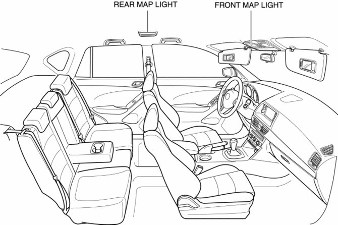
Mazda CX-5 Service & Repair Manual: Room Light Control System
Outline
-
The room light control system changes the illumination condition and illumination level of the interior lights (door position) according to whether the doors are opened/closed and locked/unlocked.
-
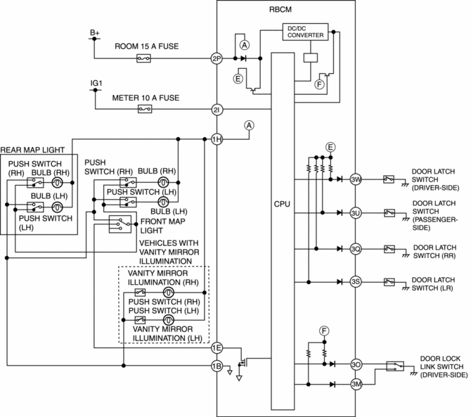
The room light control system is controlled by the rear body control module (RBCM).
-
The rear body control module (RBCM) performs room light control system fail-safe..
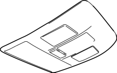
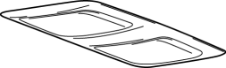
Structural View
System Wiring Diagram
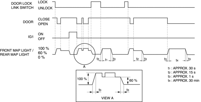
Operation
|
Operation condition |
Interior light |
Lights off condition (Any of the following conditions is met) |
|
|
Illumination period |
Brightness level |
||
|
Approx. 30 min |
100 % |
|
|
Approx. 30 s |
100 % |
|
|
Approx. 30 s |
100 % |
|
|
Approx. 15 s |
60 % |
|
*1 After the interior light is turned off according to the cancel conditions, it turns on again if any one of the following conditions is met.
-
After all doors are closed, any door is re-opened (after all door latch switches and door switches are off, any door latch switch and door switch is on)
-
Ignition is switched ON
|
Type |
Installation position |
Room light control system |
|
|
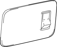
Front map light |
|
Front area of roof |
? |
|
Rear map light |
|
Center area of roof |
? |
|
Cargo compartment light |
|
Cargo compartment |
- |
|
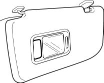
Vanity mirror illumination |
|
Sunvisor |
- |
|
Glove compartment light |
|
Passenger's side floor panel |
- |
 Purge Control
Outline
An appropriate amount of evaporative gas is fed into the intake manifold
by the purge solenoid valve operation according to the engine operation conditions.
This ensures driveabil ...
 Sas Control Module Configuration (Using As Built Data) [Standard Deployment
Control System]
Sas Control Module Configuration (Using As Built Data) [Standard Deployment
Control System]
NOTE:
If the configuration is performed using As-Built data, the set value of the
personalization function is reset to the initial value (condition when shipped
from factory). Verify the ...
Other materials:
Rear Shock Absorber Disposal
WARNING:
Whenever drilling into a rear shock absorber, wear protective eye wear. The
gas in the rear shock absorber is pressurized, and could spray metal chips into
the eyes and face when drilling.
1. Clamp a rear shock absorber on a flat surface or with the piston pointing
...
Purge Solenoid Valve Removal/Installation
1. Disconnect the negative battery cable..
2. Remove the plug hole plate..
3. Remove the air cleaner and air hose as a single unit..
4. Disconnect the high pressure fuel pump connector.
5. Disconnect the harness clip as shown in the figure.
6. Remove in the order indicated in the table ...
Construction Standard Values [Construction Standard Values]
Front view
No.
Measurement part
Standard values (mm {in})
Maximum values (mm {in})
Minimum values (mm {in})
Side by difference (mm {in})
A
1
5.0
{0.20}
7.0
{ ...
