Mazda CX-5 Service & Repair Manual: Steering Gear And Linkage Assembly
CAUTION:
-
To prevent damage to the steering gear, secure it to the vise using a copper plate or clean cloth.
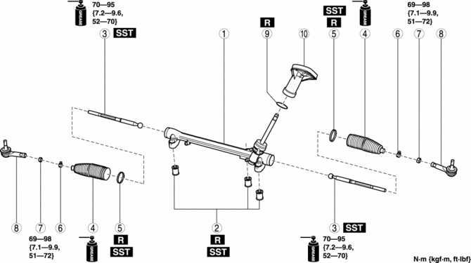
1. Assemble in the order shown in the figure.
|
1 |
Steering gear |
|
2 |
Mounting rubber (See Mounting Rubber Assembly Note.) |
|
3 |
Tie rod (See Tie Rod Assembly Note .) |
|
4 |
Boot |
|
5 |
Boot band (See Boot Band Assembly Note .) |
|
6 |
Boot clamp |
|
7 |
Locknut |
|
8 |
Tie-rod end (See Tie-rod End Assembly Note.) |
|
9 |
O-ring |
|
10 |
Dust cover |
Mounting Rubber Assembly Note
1. Apply soapy water to the rubber part of the mounting rubber.
2. Press fit the ear portion of the mounting rubber (lower side) using the SSTs until it projects from the gear housing as shown in the figure.
NOTE:
-
Press fit the ear portion of the mounting rubber (upper side) until it partially enters the gear housing.
3. Reverse the gear housing, then press fit the mounting rubber using the SSTs and the press until the mounting rubber ear portion (upper side) contacts the gear housing.
4. Verify that both mounting rubber ears are correctly assembled with no gaps between them and the gear housing as shown in the figure.
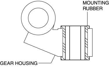
-
If there are gaps, readjust their positions using the SSTs
and the press.
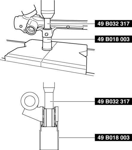
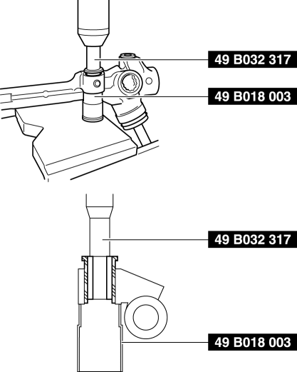
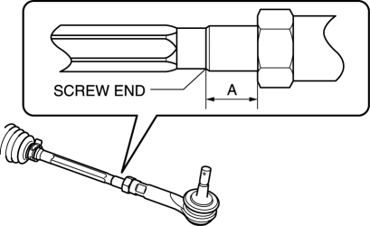
Tie Rod Assembly Note
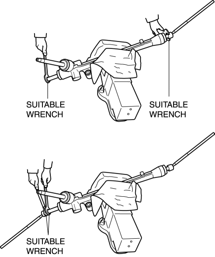
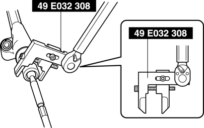
1. Lock the steering rack end (pinion gear side) against rotation with a wrench and install the tie rod using the suitable wrench.
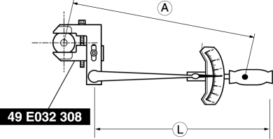
2. Combine the the SST
with the torque wrench, then measure A and L as shown in the figure.
-
A: Length from the center of the tie rod to the grip.
-
L: Length of the torque wrench.
3. Recalculate the torque by using torque formulas, then tighten the tie rod using the SST
.
CAUTION:
-
When installing a torque wrench to the SST (49 E032 308), install it perpendicular to the SST as shown in the figure. If installed incorrectly, the SST could separate from the tie rod, which could cause damage to the tie rod.
-
Tightening Torque
-
70—95 N·m {7.2—9.6 kgf·m, 52—70 ft·lbf}
|
Torque unit |
Formula |
|
NВ·m |
NВ·mГ—[L/A] |
|
kgfВ·m |
kgfВ·mГ—[L/A] |
|
ftВ·lbf |
ftВ·lbfГ—[L/A] |
Boot Band Assembly Note
1. Assemble the boot band to the boot.
2. Crimp the boot band using the SST
.
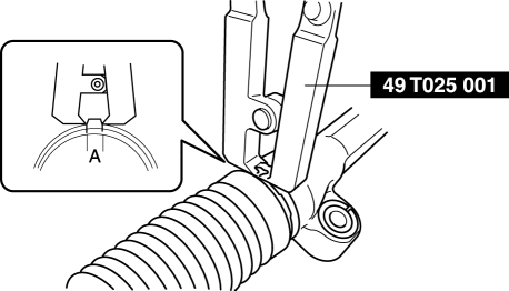
3. Verify that the crimping clearance A is within the specification.
-
If crimping clearance A exceeds the specification, reduce SST
clearance, and crimp the boot band again.
-
If crimping clearance A is less than the specification, increase SST
clearance, and crimp a new boot band.
-
Standard clearance A
-
2.5—3.0 mm {0.10—0.11 in}
4. Rotate the by hand and verify that it is securely installed to the boot band.
Tie-rod End Assembly Note
1. Align the alignment marks made before removal and assemble the tie-rod end to the tie rod.
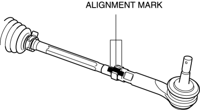
-
If there are no alignment marks, go to the next step.
2. Adjust dimension A shown in the figure to the standard, then assemble the tie-rod end.
-
Standard Dimension A
-
10.1—23.1 mm {0.398—0.909 in}
 Steering Gear And Linkage
Purpose/ Function
The rotational movement input from the intermediate shaft is converted to
a linear movement in the horizontal direction of the steering rack by the rack
and pinion mecha ...
 Steering Gear And Linkage Disassembly
CAUTION:
To prevent damage to the steering gear, secure it to the vise using a copper
plate or clean cloth.
1. Disassemble in the order indicated in the figure.
1
...
Other materials:
Front Seat Removal/Installation
WARNING:
Handling a side air bag improperly can accidentally operate (deploy) the
air bag, which may seriously injure you. Read the service warnings/cautions
in the Workshop Manual before handling the front seat (side air bag integrated)..
If the sliding mechanisms on both side ...
Rear Side Frame Removal [Panel Replacement]
Symbol Mark
Removal Procedure
NOTE:
When drilling the 35 locations indicated by (A) and 4 locations indicated
by (C) shown in the figure, do not drill a hole all the way through or there
could be a problem when installing the new part.
1. Drill the 35 locations indicated by ...
Clock Spring Adjustment [Standard Deployment Control System]
1. Set the front wheels straight ahead.
CAUTION:
The clock spring will break if over?wound. Do not forcibly turn the clock
spring.
2. Turn the clock spring clockwise until it stops.
3. Turn the clock spring counterclockwise approx. 2 turns.
4. Align the mark on the clo ...
