
Mazda CX-5 Service & Repair Manual: Roof Carrier Bracket Removal/Installation
1. Disconnect the negative battery cable..
2. Remove the following parts:
a. Sunroof seaming welt (with sunroof system).
b. A-pillar trim.
c. Front map light.
d. Sunvisor.
e. Front scuff plate.
f. Rear scuff plate.
g. B-pillar lower trim.
h. Adjust anchor cover.
i. Upper anchor installation bolt on the seat belt.
j. B-pillar upper trim.
k. Assist handle.
l. Trunk board.
m. Trunk end trim.
n. Trunk side trim.
o. D-pillar trim.
p. C-pillar trim.
q. Headliner.
3. Remove nuts.
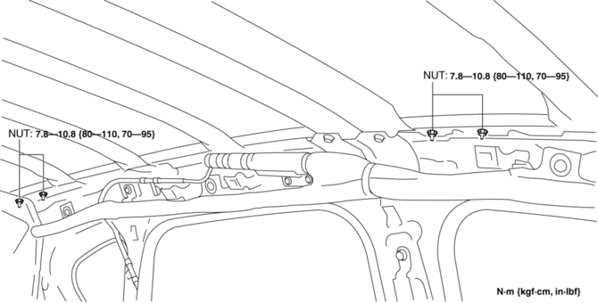
4. Remove the roof carrier brackets.
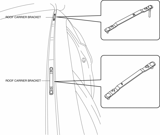
5. Install in the reverse order of removal.
NOTE:
-
Install the roof carrier bracket so that the F on it faces vehicle front. (front side)
-
Install the roof carrier bracket so that the R on it faces vehicle rear. (rear side)
 Rear Differential Removal/Installation
WARNING:
When replacing the coupling component, read the special character string
before installing a new coupling component and write it to the AWD control module
after replacement. The ...
 Driveshafts
...
Other materials:
Sunroof Switch Inspection
1. Disconnect the negative battery cable..
2. Remove the front map light..
3. Verify that the continuity between the sunroof switch terminals is as indicated
in the table.
If not as indicated in the table, replace the sunroof switch.
...
DSC Related Parts Sensor Initialization Procedure
WARNING:
If the initialization procedure is not completed, the DSC will not operate
properly and it might cause an unexpected accident. Therefore, after replacing
or removing the DSC HU/CM or SAS control module, make sure to perform the initialization
procedure to insure proper DSC ...
PID/Data Monitor Inspection [Two Step Deployment Control System]
1. Connect the M-MDS to the DLC-2.
2. After the vehicle is identified, select the following items from the initialization
screen of the M-MDS.
a. Select “DataLogger”.
b. Select “Modules”.
c. Select “RCM”.
3. Select the applicable PID from the PID table.
4. Verify the PID da ...
