Mazda CX-5 Service & Repair Manual: Refrigerant Pressure Sensor Inspection [Full Auto Air Conditioner]
1. Install the manifold gauge.
2. Verify the high-pressure side reading of the manifold gauge.
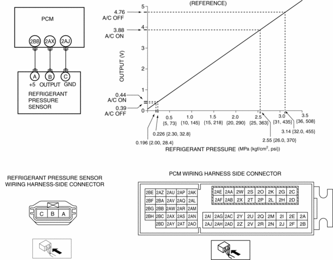
3. Measure the terminal voltage at PCM terminal 2BB, 2AX and 2AJ
4. Using the graph below, measure and verify the terminal voltages at 2AX.
5. Follow the PCM inspection when measuring the other terminal voltages..
-
Terminal 2BB: Approx. 5 V (Ignition switch on)
-
Terminal 2AJ: 1.0 V or less
-
If the each voltage is not normal, inspect the related wiring harness.
-
If there is any malfunction, replace the related wiring harness.
-
If wiring harness is normal, replace the refrigerant pressure sensor.

 Refrigerant Pressure Check
NOTE:
Measure the refrigerant pressure after approx.10 min have elapsed
from engine start.
1. Install the manifold gauge..
2. Start the engine and warm it up.
3. Set the fan speed ...
 Refrigerant Pressure Sensor Inspection [Manual Air Conditioner]
1. Install the manifold gauge.
2. Verify the high-pressure side reading of the manifold gauge.
3. Measure the terminal voltage at PCM terminals 2BB, 2AX and 2AJ
4. Using the graph below, measure ...
Other materials:
Propeller Shaft Removal/Installation
CAUTION:
If the constant velocity joint is bent during propeller shaft removal/installation
or transportation after servicing, the constant velocity joint boot may contact
the metallic cover and the boot may be damaged. Insert a rag between the boot
and the metallic cover before ser ...
Rear Brake (Disc) Removal/Installation
1. Loosen the adjusting nut..
2. Remove in the order indicated in the table.
3. Install in the reverse order of removal.
4. After installation, add brake fluid, bleed the air, and inspect for fluid
leakage..
5. Pump the brake pedal a few times and inspect the following:
The disc pa ...
Service Cautions
Injury/damage Prevention Precautions
Depending on the vehicle, the cooling fan may operate suddenly even when
the ignition is switched to off. Therefore, keep hands and tools away from the
cooling fan even if the cooling fan is not operating to prevent injury to personnel
or damage t ...
