Mazda CX-5 Service & Repair Manual: Keyless Warning Alarm
Purpose
-
The keyless warning alarm notifies the driver that the remote transmitter cannot be verified or the steering lock cannot be released.
Function
-
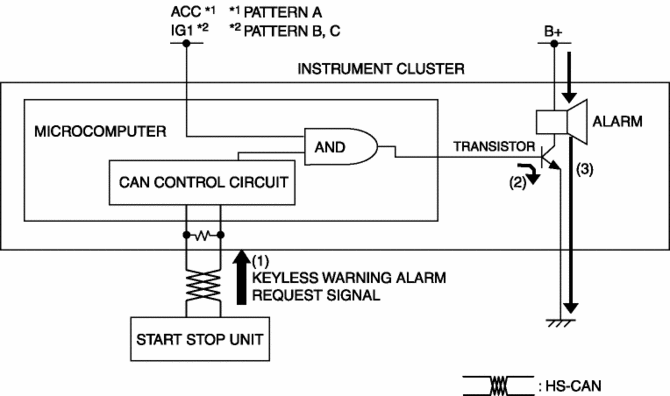
When the instrument cluster receives the keyless warning alarm request signal sent from the start stop unit via the CAN signal, the keyless warning alarm sounds.
-
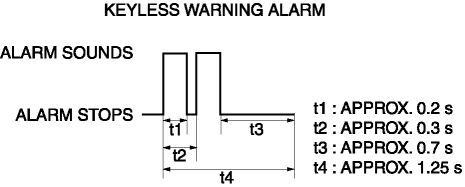
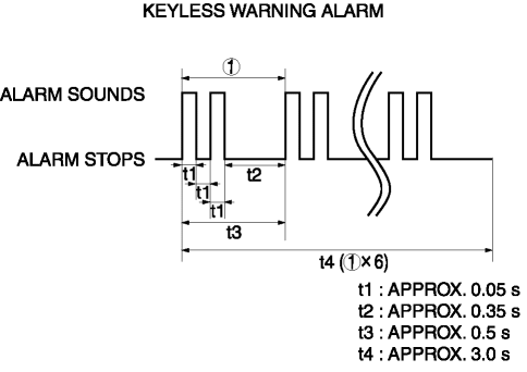
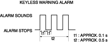
The keyless warning alarm sound pattern is as shown in the figure. For the conditions that the alarm for each pattern sounds, refer to KEYLESS ENTRY SYSTEM (without advanced keyless entry system)/ADVANCED KEYLESS ENTRY SYSTEM (with advanced keyless entry system).
Pattern A
Pattern B
Pattern C
Construction
-
The keyless warning alarm sounds using the buzzer built into the instrument cluster.
Operation
1. The instrument cluster receives (1) the keyless warning alarm request signal from the start stop unit.
2. The instrument cluster microcomputer turns the transistor on (2) based on the keyless warning alarm request signal.
3. When the transistor turns on, the ground circuit of the alarm is established and the alarm sounds (3).
Fail-safe
-
Function not equipped.
 Keyless Beeper Removal/Installation
1. Disconnect the negative battery cable..
2. Remove the cowl grille..
3. Disconnect the connector.
4. Pull the keyless buzzer in the direction of the arrow (2) shown in the figure
while p ...

Other materials:
Rear Drive Shaft Removal/Installation
CAUTION:
Performing the following procedures without first removing the ABS wheel?speed
sensor may possibly cause an open circuit in the harness if it is pulled by
mistake. Before performing the following procedures, remove the ABS wheel?speed
sensor (wheel side) and fix it to an ...
Front Seat
Seat Operation
1 Seat Slide
(Manual Seat) To move a seat forward or backward, raise the lever and slide
the seat to the desired position and release the lever.
Make sure the lever returns to its original position and the seat is locked in
place by attempting to push it forward and backward. ...
Tcs Control
Outline
The TCS control actuates torque reduction through engine control, as well
as using brake control to control traction.
NOTE:
Engine control: Engine output is lowered by fuel cut and ignition timing
control to reduce the traction, preventing driving wheel slip.
...
