Mazda CX-5 Service & Repair Manual: Front Door Key Cylinder Switch Inspection
1. Perform the front door glass preparation..
2. Disconnect the negative battery cable..
3. Remove the following parts:
a. Inner garnish.
b. Front door trim.
c. Front door key cylinder.
d. Front door glass.
e. Front door module panel.
f. Front door latch and lock actuator.
Front Door Key Cylinder Switch Lock-Side Inspection
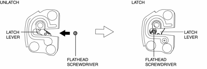
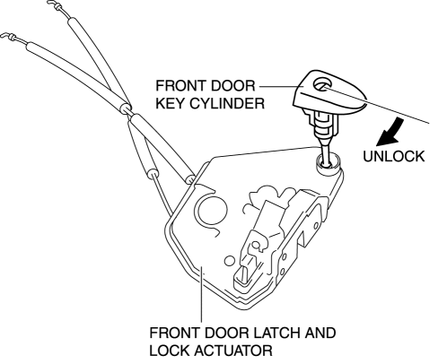
1. Press in the latch lever of the front door latch and lock actuator using a flathead screwdriver, and set it to the latched condition.
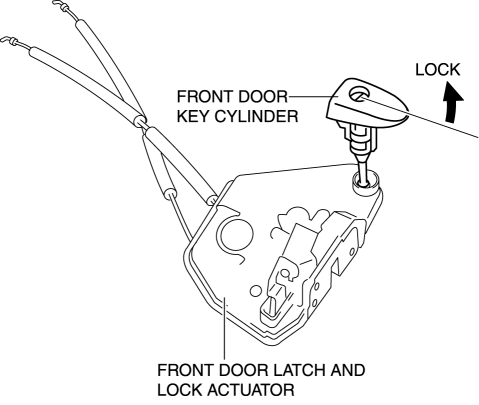
2. Rotate the front door key cylinder in the direction of the arrow until it stops to set the front door key cylinder switch to the locked condition.
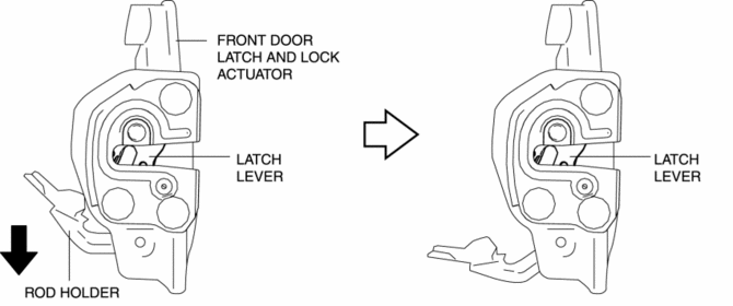
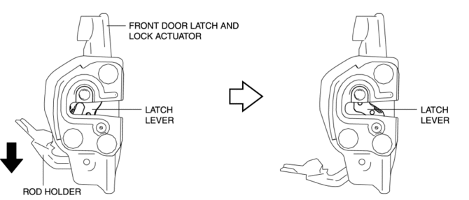
3. To verify that the switch is in the locked position, press down the rod holder in the direction of the arrow and verify that the latch lever does not move.
NOTE:
-
If the latch lever moves, the front door key cylinder switch is not in the locked position. Repeat the procedure from Step 1.
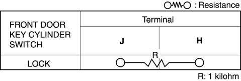
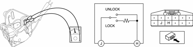
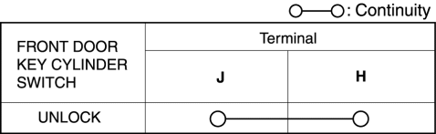
4. Verify that the continuity of the front door key cylinder is as indicated in the table.
-
If not as indicated in the table, replace the front door latch and lock actuator.
Front Door Key Cylinder Switch Unlock-Side Inspection
1. Press in the latch lever of the front door latch and lock actuator using a flathead screwdriver, and set it to the latched condition.
2. Rotate the front door key cylinder in the direction of the arrow until it stops to set the front door key cylinder switch to the unlocked condition.
3. To verify that the switch is in the unlocked position, press down the rod holder in the direction of the arrow and verify that the latch lever moves.
NOTE:
-
If the latch lever does not move, the front door key cylinder switch is not in the unlocked position. Repeat the procedure from Step 2.
4. Verify that the continuity of the front door key cylinder is as indicated in the table.
-
If not as indicated in the table, replace the front door latch and lock actuator.
 Front Door Key Cylinder Removal/Installation
1. Disconnect the negative battery cable..
2. Remove the service hole cover.
3. Detach the screw from the front door key cylinder.
NOTE:
The screw cannot be removed because the f ...
 Key Cylinder Switch
Purpose
The switch turns on/off in conjunction with the front door key cylinder lock/unlock
and the rear body control module (RBCM) detects the key cylinder operation condition
by the cha ...
Other materials:
Differential Oil Temperature Sensor Removal/Installation
WARNING:
Hot differential oil may cause severe burns. Do not perform maintenance while
differential oil is hot.
1. Disconnect the negative battery cable.
2. Disconnect the differential oil temperature sensor connector.
3. Remove the differential oil temperature sensor.
4. ...
Blower Unit Removal/Installation
1. Disconnect the negative battery cable..
2. Remove the following parts:
a. Front scuff plate (passenger-side).
b. Front side trim (passenger-side).
c. Dashboard under cover.
d. Glove compartment.
e. Decoration panel.
f. Lower panel (passenger-side).
3. Disconnect the blower motor c ...
Supplemental Restraint System Components
1 Driver/Front passenger inflators and air bags
2 Roll-over sensorí, crash sensors, and diagnostic module (SAS unit)
3 Front seat belt pretensioners
4 Front air bag sensors
5 Side crash sensors
6 Air bag/front seat belt pretensioner system warning light
7 Side and curtain inflators ...
