Mazda CX-5 Service & Repair Manual: Relay And Fuse Block
Purpose
-
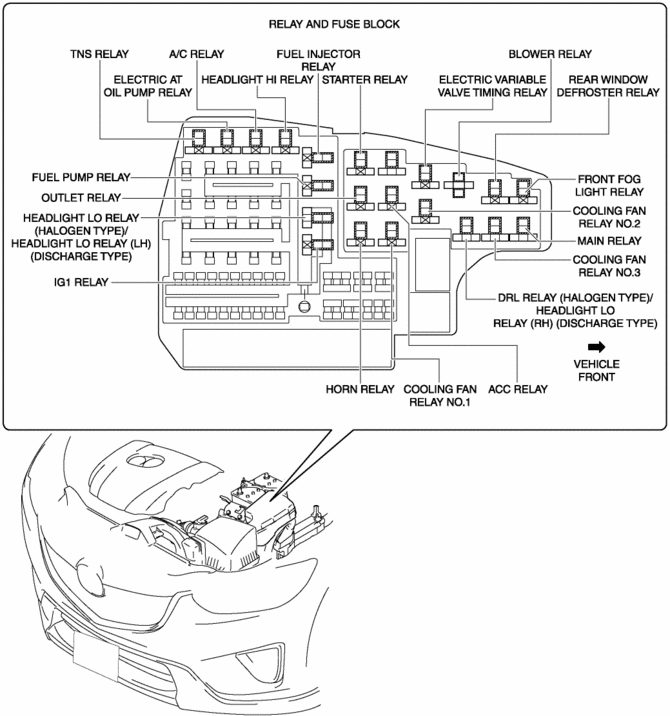
Relays and fuses used by each system are grouped and housed together for smooth inspection and replacement servicing.
Function
-
Relays and fuses used by each system are grouped and housed together.
Construction
-
Installed in the engine compartment.

Operation
Relay operation
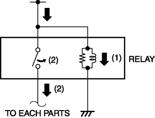
1. When electric current flows to the coil, electromagnetic power is generated.
2. The switch is attracted by the generated electromagnetic power and it switches on.
3. Electric current flows to each part that is downstream of the switch.

Fuse operation
1. If electric current to each fuse is the specified value or more, the fuse melts due to heat generation.
2. Interrupts electric current flow downstream of the fuse.
Fail-safe
-
Function not equipped.
 Electrical System
Electrical Parts
Battery cable
Before disconnecting connectors or removing electrical parts, disconnect
the negative battery cable.
Wiring Harness
To remove the wiring ha ...
 Relay And Fuse Block Disassembly/Assembly
1. Insert a tape-wrapped flathead screwdriver into the service hole in the position
shown in the figure.
2. Move the flathead screwdriver in the direction of the arrow (1) shown in the
figur ...
Other materials:
Brake System/ABS Warning Light
Purpose/Function
The brake system/ABS warning light is built into the instrument cluster.
If a malfunction is detected in the system with the parking brake released,
the warning light illuminates to notify the driver.
Construction/Operation
When the DSC system and CAN l ...
Air Bag Module And Pre Tensioner Seat Belt Deployment Procedures [Standard Deployment
Control System]
WARNING:
A live (undeployed) air bag module or pre-tensioner seat belt may accidentally
operate (deploy) when it is disposed of and cause serious injury. Do not dispose
of a live (undeployed) air bag module or pre-tensioner seat belt. If the SSTs
(Deployment tool and Adapter harness ...
Electric Variable Valve Timing Control
Outline
The PCM determines the optimum intake valve timing according to the engine
operation conditions, and sends the motor drive signals to the electric variable
valve timing driver. With the adoption of the electric drive system, variable
intake valve timing can be controlled with ...
