Mazda CX-5 Service & Repair Manual: Efficient Installation Of Body Panels
Checking Preweld Measurements And Watching
-
Align to the standard reference dimensions, based upon the body dimensions illustration, so that new parts are installed in the correct position.

Welding Notes
-
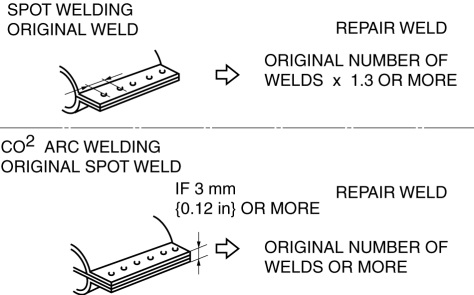
For the number of weld points, welding should be performed in accordance with the following reference standards.
Spot Welding Notes
-
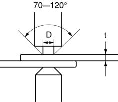
The shape of the spot welder tip is D=(2?t)+3. If the upper panel thickness is different from that of the under panel, adjust to the thinner one.
-
Because the weld strength is affected by the shape of the spot welder tip, the optimum condition of the tip should always be maintained.
-
Spot welds should be made at points other than the originally welded points.
-
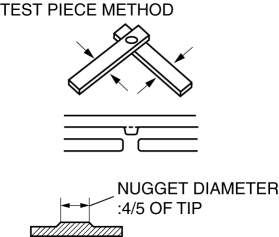
Before spot welding, make a trial weld using the same material as the body panel to check the weld strength.
Checking Weld Strength
-
Installation locations of the engine, chassis, and seat belts are designated as important safety locations for weld strength. Check weld strength by driving a chisel between the panels at every fourth or fifth weld spot, and every tenth regular weld location.
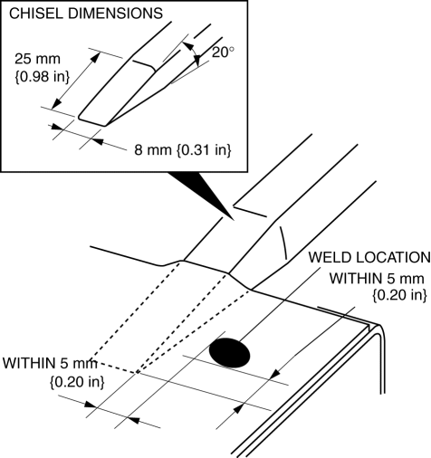
-
Drive the chisel between the panels according to the number of panels as shown below.
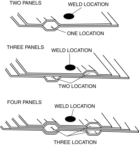
-
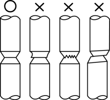
To determine weld strength, drive the chisel between the panel and check whether the panels come apart. If the panels come apart, make another weld near the original weld.
-
Restore the shape of the checked area.
 D Pillar Reinforcement (Lower) Removal [Panel Replacement]
Symbol Mark
Removal Procedure
1. Drill the 8 locations shown in the figure.
2. Remove the D-pillar reinforcement (lower). ...
 Efficient Removal Of Body Panels
Body Measurements
Before removal or rough?cutting, first measure the body at and around the
damaged area against the standard reference dimension specifications. If there
is deformation, ...
Other materials:
Service Publications
Service Publications
Factory-authorized Mazda service publications are available for owners who wish
to do some of their own maintenance and repair.
When requesting any of our publications through an Authorized Mazda Dealer, refer
to the chart below.
If they do not have what you need in stock ...
Manual Type
Control Switches
Temperature control dial
This dial controls temperature. Turn it clockwise for hot and counterclockwise
for cold.
NOTE
When the mode is set to or with the fan control dial in a position other than
0 and the temperature control dial in the maximum cold position, the air int ...
Lubrication System
Outline
Pressure loss is reduced by optimizing the oil passage.
With the adoption of the chain drive type oil pump, oil pump drive force
has been reduced.
With the adoption of the oil shower pipe, sliding resistance has been reduced.
With the adoption of the engine ...
