Mazda CX-5 Service & Repair Manual: Crankshaft, Main Bearing
Purpose, Function
-
The crankshaft converts the reciprocating movement of the piston to a rotational movement via the connecting rod.
-
The main bearing forms an oil film on the outer surface of the crankshaft journal to prevent wear due to sliding.
Construction
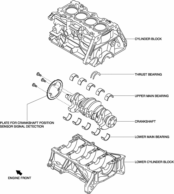
Crankshaft
-
The crankshaft is installed to the inside (crankcase) of the cylinder block.
-
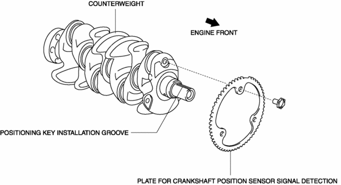
The crankshaft has a key groove to match timing to the crankshaft pulley.
-
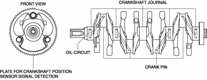
The crankshaft has the following parts shown in the figure.
-
The optimized shaft diameter ratio of the crankshaft journal and crank pin has reduced sliding resistance while maintaining rigidity.
-
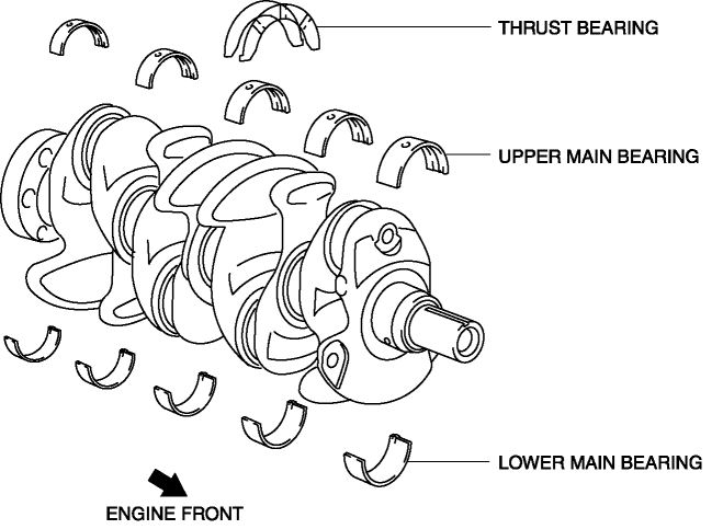
The steel crankshaft has five bearings and eight counterweights for improved accuracy in the rotational balance.
-
The crankshaft journal and crank pin have been induction hardened* to bear high loads.
-
The crankshaft has an oil passage for supplying engine oil to the crankshaft journal and crank pin.
Main bearing
-
The main bearing is installed to the outer surface of the crankshaft journal.
-
The upper main bearing and lower main bearing are made of aluminum alloy.
-
The upper main bearing has an oil groove and oil hole.
-
Thrust force is suppressed by the thrust bearings on both sides of the No.3 journal.
 Crankshaft Position (CKP) Sensor
Purpose/Function
Detects the crankshaft speed as basic information for mainly determining
the fuel injection timing and ignition timing.
Detects the crankshaft speed and inputs it to ...
 Motor Mounts
...
Other materials:
St 001/12 Special Service Tool Shipment January 2013
APPLICABLE MODEL(S)/VINS
2014 Mazda6
2014 CX-5
DESCRIPTION/PRICING
In support of the new 2014 Mazda6 and the 2014 CX-5, Mazda will ship to all dealers
one (1) new Special Service Tool (SST). The SST will be shipped automatically by
Mazda’s tool vendor, SPX during January 2013.
The followi ...
Instrumentation/Driver Info.
Outline
An LCD has been adopted to the instrument cluster which displays the ambient
temperature, trip computer, and odometer/tripmeter.
A blind spot monitoring (BSM) system has been adopted which notifies the
driver of vehicles approaching from behind on the left or right adjac ...
Blower Motor [Full Auto Air Conditioner]
Purpose
The blower motor sends airflow into the cabin.
Function
The blower motor rotates the blower fan to create airflow and sends out the
airflow in the blower unit and A/C unit.
Construction
The blower motor is installed to the blower unit.
The blower m ...
