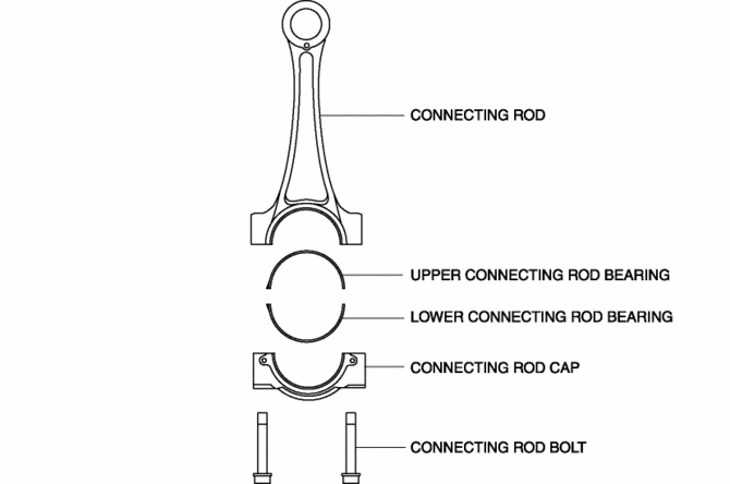
Mazda CX-5 Service & Repair Manual: Connecting Rod, Connecting Rod Bearing
Purpose, Function
Connecting rod
-
The connecting rod transmits the reciprocating movement of the piston to the crankshaft by engaging the piston pin and crank pin.
Connecting rod bearing
-
The connecting rod bearing forms an oil film on the outer surface of the crank pin to prevent wear due to sliding.
Construction
Connecting rod
-
The connecting rod is installed between the piston pin and crank pin.
-
High-strength, forged carbon steel has been adopted for weight reduction.
-
A cracking method*1 for breaking off and separating the connecting rod from the connecting rod cap has been adopted for improved accuracy.
-
Weight has been reduced by optimizing the shape from the I shaft to the large end.
-
Reciprocating inertial weight, including the piston, has been reduced with the use of a full-float type for the connection with the piston and further tapering of the small end shape.
-
With the adoption of the plastic region tightening*2 method for the connecting rod bolt, the stability of the axial force has been improved.

*2 Plastic region tightening is a method of controlling the tightening using the rotation angle of a bolt. By tightening to the region (plastic tightening region) in which bolt deformation does not become irreversible, variation in axial force is suppressed.
Connecting rod bearing
-
The connecting rod bearing is installed on the outer surface of the crank pin.
-
The upper and lower connecting rod bearing are made of aluminum alloy.
 Piston Assembly
...
 Piston, Piston Ring, Piston Pin
Purpose, Function
Piston
The piston in the cylinder of the cylinder block moves reciprocally by the
pressure received when the air-fuel mixture combusts.
Piston ring
The piston ...
Other materials:
Drive Belt Removal/Installation [Skyactiv G 2.0]
WARNING:
A hot engine can cause severe burns. Turn off the engine and wait until it
is cool before servicing.
NOTE:
Remove/install the drive belt from the underside of the vehicle.
Generator Drive Belt Removal/Installation
CAUTION:
To prevent damage to the dri ...
Rear Stabilizer Removal/Installation [Awd]
WARNING:
Verify that the rear crossmember is securely supported by a jack. If the
rear crossmember falls off, it can cause serious injury or death, and damage
to the vehicle.
CAUTION:
Performing the following procedures without first removing the rear ABS wheel-spee ...
Clutch Disc Inspection [C66 M R]
Operation Inspection
1. Inspect the lining surface for discoloration and grease adhesion.
2. Inspect the torsion spring for weakness and the rivets for looseness.
3. Using a vernier caliper, measure the depth between the lining surface and
the rivet head.
Minimum clutch disc thicknes ...
