Mazda CX-5 Service & Repair Manual: Climate Control Unit [Manual Air Conditioner]
Purpose
-
The climate control unit performs air conditioning according to the operation by the users and the driving conditions of the vehicle.
Function
-
The climate control unit determines optimum air-conditioning based on the input signals from each sensor and the control module and the operation signals from the control panel, and controls each actuator, A/C compressor, and the blower motor..
Construction
-
A wire-type climate control unit has been adopted.
-
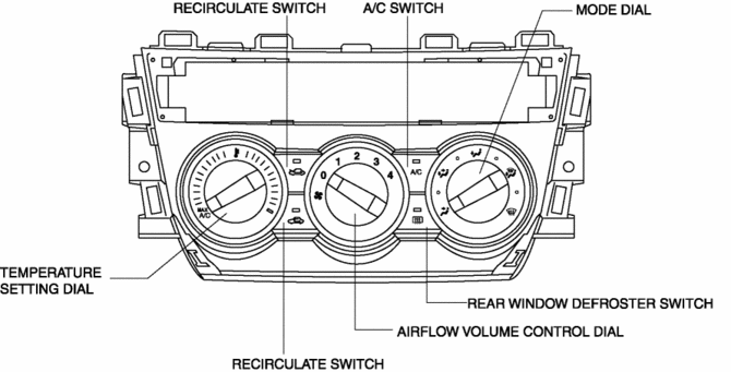
The climate control unit consists of a control panel and a control unit.
-
The switches and dials shown in the figure are positioned on the control panel.
Operation
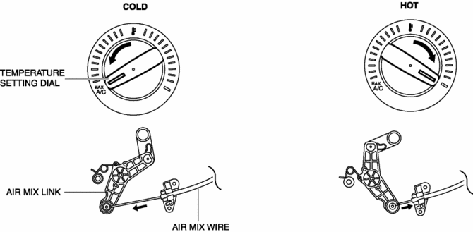
Airflow temperature setting
-
When the temperature control dial is turned, the length of the air mix wire is changed, and the air mix door position is switched via the air mix link. As a result, the blower air temperature is changed..
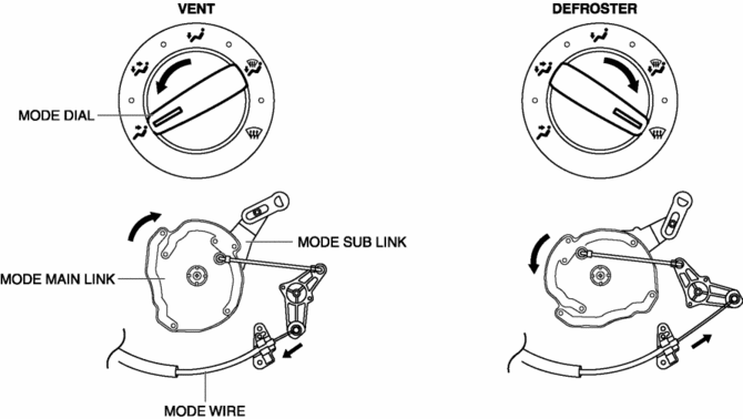
Airflow mode setting
-
When the mode dial is turned, the length of the airflow mode wire is changed, and the airflow mode door position is switched via the airflow mode main link and the airflow mode sub link. As a result, the airflow mode is changed..
Fail-safe
-
Function not equipped.
 Climate Control Unit Removal/Installation [Manual Air Conditioner]
Removal
1. Disconnect the negative battery cable..
2. Remove the following parts:
a. Shift lever knob (MTX).
b. Glove compartment.
c. Front console box.
d. Shift panel.
e. Upper panel.
...
 Condenser
Purpose
The condenser cools the high-temperature, highly pressurized refrigerant.
Function
The condenser cools the high-temperature, highly pressurized gaseous refrigerant
compr ...
Other materials:
Light Switch Removal/Installation
NOTE:
When removing the light switch, it is necessary to rotate the steering wheel.
If the ignition is switched off from ON (engine on) with the driver's door closed,
the steering wheel is locked. Therefore, perform the procedure in Steps 1 to
3 so that the steering wheel is not ...
Rear Window Glass Installation
WARNING:
Using a utility knife with bare hands can cause injury. Always wear gloves
when using a utility knife.
CAUTION:
Proper installation of the glass may be difficult if sealant is cracked or
the glass is pushed out by air pressure when a door is opened/closed with al ...
Storage Compartments
WARNING
Keep storage boxes closed when driving:
Driving with the storage boxes open is dangerous. To reduce the possibility of
injury in an accident or a sudden stop, keep the storage boxes closed when driving.
CAUTION
Do not leave lighters or eyeglasses in the storage boxes while parked under ...
