Mazda CX-5 Service & Repair Manual: Antenna Feeder No.3 Removal/Installation
1. Disconnect the negative battery cable..
2. Remove the following parts:
a. B-pillar lower trim.
b. Front seat belt adjusting cover.
c. Front seat belt upper anchor installation bolt.
d. B-pillar upper trim.
e. Trunk board.
f. Trunk end trim.
g. Trunk side trim.
h. D-pillar trim.
i. C-pillar trim.
j. Liftgate upper trim (with SIRIUS satellite radio system).
3. Remove the rear passenger's assist handle..
4. Partially peel back the headliner.
NOTE:
-
If the headliner is peeled back excessively, the headliner could become creased. Be careful not to peel back the headliner excessively.
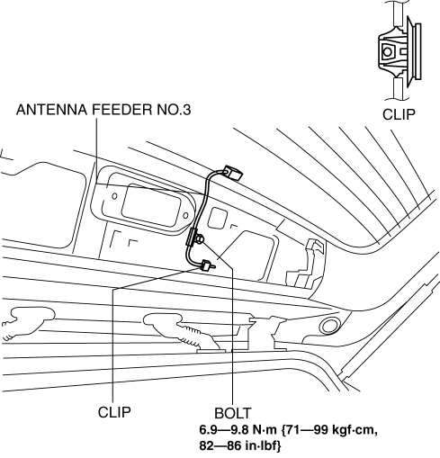
5. Disconnect antenna feeder No.2.
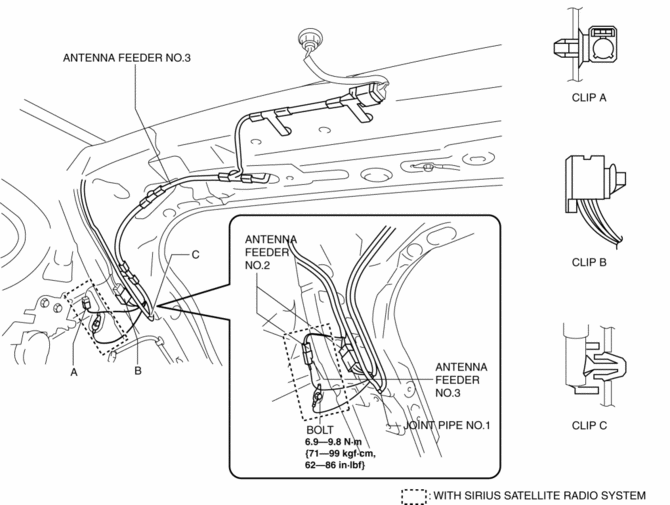
6. Remove the bolt.
7. Remove clips A and B.
8. Remove joint pipe No.1 clip.
9. Remove clips D and E.
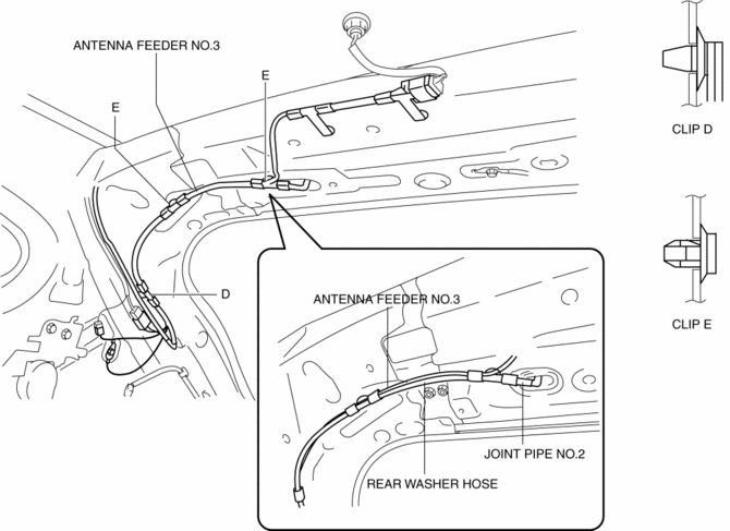
10. Disconnect joint pipe No.2.
11. Remove clips F and G.
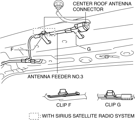
12. Disconnect the center roof antenna.
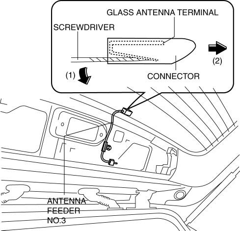
13. Using a screwdriver wrapped in protective tape, pull the connector in the direction of the arrow (2) shown in the figure while pressing glass antenna terminal in the direction of the arrow (1) shown in the figure, and disengage the glass antenna terminal from the connector. (with SIRIUS satellite radio system)
14. Disconnect the connector. (with SIRIUS satellite radio system)
15. Remove the bolt. (with SIRIUS satellite radio system)
16. Remove the clip. (with SIRIUS satellite radio system)
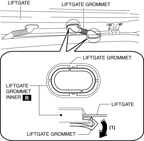
17. Partially peel the liftgate grommet in the direction of arrow (1) shown in the figure, and remove the liftgate grommet from the liftgate grommet inner. (with SIRIUS satellite radio system)
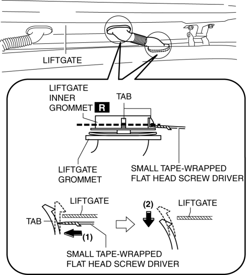
18. Using a screwdriver wrapped in protective tape, pull the liftgate grommet in the direction of the arrow (2) shown in the figure while pressing the liftgate grommet inner tab in the direction of the arrow (1) shown in the figure, and disengage the liftgate from the liftgate grommet. (with SIRIUS satellite radio system)
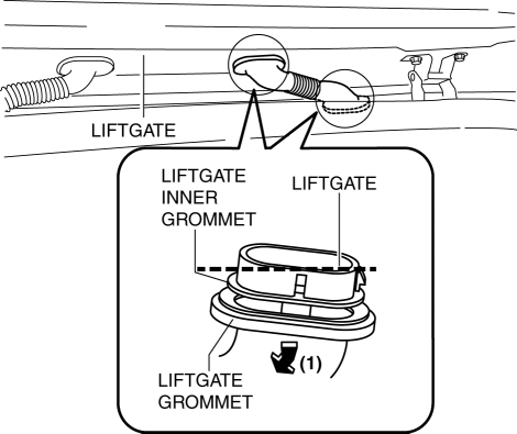
19. Pull the liftgate grommet in the direction of the arrow (1) shown in the figure and remove it.
20. Pull out the disconnected connectors of the liftgate side and vehicle interior side and antenna feeder No.3. (with SIRIUS satellite radio system)
21. Remove antenna feeder No.3.
22. Install in the reverse order of removal.
 Antenna Feeder No.3 Inspection
1. Disconnect the negative battery cable..
2. Remove the following parts:
a. Front scuff plate.
b. Rear scuff plate.
c. B-pillar lower trim.
d. Front seat belt adjusting cover.
e. Front se ...
 Audio Amplifier
Purpose, Function
The audio signal (analog voltage waveform) output from the unit equipped
on the vehicle is converted into a digital pulse. The converted digital pulse
signal is amplifie ...
Other materials:
Hazard Warning Flasher
The hazard warning lights should always be used when you stop on or near a roadway
in an emergency.
The hazard warning lights warn other drivers that your vehicle is a traffic hazard
and that they must take extreme caution when near it.
Depress the hazard warning flasher and all the turn sig ...
Dashboard Removal/Installation
1. Disconnect the negative battery cable..
2. Remove the following parts:
a. Windshield wiper arm and blade.
b. Cowl grille.
c. Windshield wiper motor.
d. Front scuff plate.
e. Front side trim.
f. Glove compartment.
g. Dashboard under cover.
h. Decoration panel.
i. Center panel. ...
Magnetic Clutch Adjustment [Full Auto Air Conditioner]
1. Measure the clearance around the entire circumference between the pressure
plate and A/C compressor pulley using a thickness gauge.
2. Verify the clearance.
If not within the specification, remove the pressure plate and adjust the
clearance by changing the shim (0.2 mm {0.008 i ...
