Mazda CX-5 Service & Repair Manual: Quick Release Connector (Emission System)
Purpose, Function
-
Serviceability has been improved by the easy disconnection/connection.
Construction
-
The following types of quick release connectors are used.
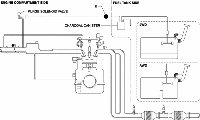
U.S.A. and CANADA
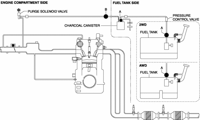
Except U.S.A and CANADA
Type A
-
An SST is not used with this type.
-
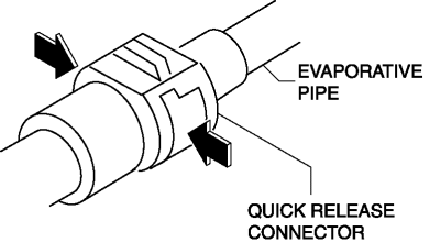
Consists of a retainer and O-ring. The quick release connector is integrated with the evaporative hose and therefore cannot be disassembled.
-
To connect the quick release connector properly, push it into the evaporative pipe until a click sound is heard.
-
New quick release connectors are fitted with a checker tab that prevent improper installation. This checker tab cannot normally be removed. When the quick release connector is properly connected to the evaporative pipe, the lock is released and the checker tab comes off. Due to this, it can be verified that the quick release connector is completely connected.
Type B
-
An SST is not used with this type.
-
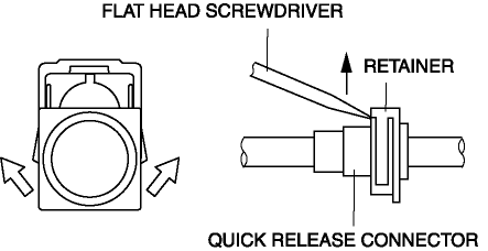
Mainly consists of a retainer and O-ring. The quick release connector is integrated with the evaporative hose and therefore cannot be disassembled.
-
When the quick release connector is connected, the evaporative pipe projection is locked at the clamp lock point. To release the quick connector lock for each type, follow the procedure in the order shown in each figure.
 Quick Release Connector (Emission System) Removal/Installation
Quick Release Connector Type and Position
CAUTION:
Verify the type and location, and install/remove properly.
U.S.A. and CANADA
Except U.S.A. and CANADA
Type A Removal
CAUTIO ...
 Rollover Valve
Purpose, Function
Prevents fuel from flowing into the evaporative gas passage during sudden
cornering or vehicle rollover.
Construction
The rollover valve is built into the fuel ...
Other materials:
Heater Core Inspection
1. Inspect the heater core for damage, cracks, and water leakage.
If there is any malfunction, replace the heater core.
2. Visually inspect the fins for bending.
If there is any bending, use the end of a flathead screwdriver to straighten
the fins.
3. Visually inspect ...
Liquid Crystal Display (LCD)
Outline
The LCD displays vehicle information in the instrument cluster.
The instrument cluster performs LCD fail-safe..
Function/Construction
The instrument cluster configures the indication of the LCD based on the
CAN signals sent from the related modules and displays ...
Front Frame (Rear) Removal [Panel Replacement]
Symbol Mark
Removal Procedure
1. Drill the 33 locations shown in the figure.
NOTE:
When drilling, do not drill a hole all the way through or there could be
a problem when installing the new part.
2. Remove the front frame (rear). ...
