Mazda CX-5 Service & Repair Manual: Clock Spring Inspection [Standard Deployment Control System]
1. Disconnect the negative battery cable and wait for 1 min or more
..
2. Remove the driver?side air bag module..
3. Remove the steering wheel..
4. Remove the column cover..
5. Remove the clock spring..
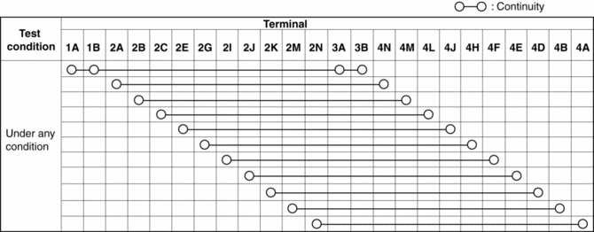
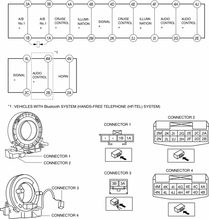
6. Verify that the continuity is as indicated in the table.
-
If not as indicated in the table, replace the clock spring.
NOTE:
-
When the vehicle-side connector for the clock spring is disconnected, terminals 1A and 1B are shorted to prevent unexpected operation (deployment) of the air bag module.


 Clock Spring Adjustment [Two Step Deployment Control System]
1. Set the front wheels straight ahead.
CAUTION:
The clock spring will break if over?wound. Do not forcibly turn the clock
spring.
2. Turn the clock spring clockwise until it stops. ...
 Clock Spring Inspection [Two Step Deployment Control System]
1. Disconnect the negative battery cable and wait for 1 min or more..
2. Remove the driver?side air bag module..
3. Remove the steering wheel..
4. Remove the column cover..
5. Remove the cloc ...
Other materials:
Transmission/Transaxle SST
1: Mazda SST number
2: Global SST number
Example
1:49 UN30 3009
2:303-009
Crankshaft damper remover
Clutch [C66M-R]
1:49 E011 1A0
2: –
Ring gear brake set
1:49 SE01 310A
2: –
Clutch disc center ...
Starting the Engine
WARNING
Radio waves from the key may affect medical devices such as pacemakers: Before
using the key near people who use medical devices, ask the medical device manufacturer
or your physician if radio waves from the key will affect the device.
NOTE
• The key must be carried because the
ke ...
Cabin Side Frame Straight Line Dimensions [Dimensions]
Point symbol
Designation
Hole diameter or bolt or nut size mm {in}
A
Front side frame outer datum hole
?12 {0.47}
B
Front fender panel installation hole
?10 {0.39}
...
