Mazda CX-5 Service & Repair Manual: Torque Box Removal [Panel Replacement]
Symbol Mark

Removal Procedure
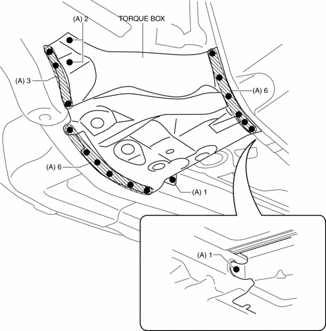
1. Drill the 19 locations indicated by (A) shown in the figure.
NOTE:
-
When drilling the 19 locations indicated by (A) shown in the figure, do not drill a hole all the way through or there could be a problem when installing the new part.

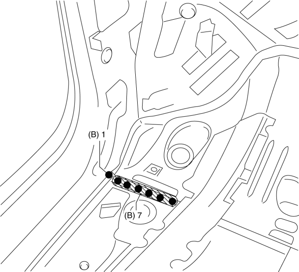
2. Drill the 8 locations indicated by (B) from the inside shown in the figure.

3. Remove the torque box.
 Torque Box Installation [Panel Replacement]
Symbol Mark
Installation Procedure
1. When installing new parts, measure and adjust the body as necessary to conform
with standard dimensions.
2. Drill holes for the plug welding before inst ...
 Ultra High Tension Steel [Construction]
Characteristics of Ultra High-Tensile Steel Plates
Ultra high-tensile steel plates have enhanced tensile strength compared to
previous high-tensile steel plates.
Because the stre ...
Other materials:
Front Door Key Cylinder Removal/Installation
1. Disconnect the negative battery cable..
2. Remove the service hole cover.
3. Detach the screw from the front door key cylinder.
NOTE:
The screw cannot be removed because the front outer handle bracket has a
stopper which prevents the screw from falling.
4. While pre ...
Traction Control System (TCS)
The Traction Control System (TCS) enhances traction and safety by controlling
engine torque and braking.
When the TCS detects driving wheel slippage, it lowers engine torque and operates
the brakes to prevent loss of traction.
This means that on a slick surface, the engine adjusts automaticall ...
Rear Crossmember Removal/Installation [Awd]
WARNING:
Verify that the crossmember is securely supported by a jack. If the rear
crossmember falls off, it can cause serious injury or death, and damage to the
vehicle.
CAUTION:
Performing the following procedures without first removing the rear ABS wheel-speed
sensor ...
