Mazda CX-5 Service & Repair Manual: Start Stop Unit
Purpose
-
Performs control of several systems based on input/output signals from switches.
Function
-
The start stop unit controls systems based on the input/output signals.
-
The functions which are controlled are as follows:
Control Table
|
Control |
Content |
Reference |
|
Advanced keyless entry system control |
Authorization of the remote transmitter being carried is automatically performed using radio waves, and all the doors lock/unlock according to the switch operation. |
(See ADVANCED KEYLESS ENTRY SYSTEM.) |
|
Keyless entry system control |
When the lock/unlock buttons on the transmitter are pressed at a distance away from the vehicle, all the doors lock/unlock. |
(See KEYLESS ENTRY SYSTEM.) |
|
Push start system control |
When the push button start is pressed, authorization of the remote transmitter brought into the vehicle is automatically performed. |
(See PUSH BUTTON START SYSTEM [ADVANCED KEYLESS ENTRY SYSTEM].) (See PUSH BUTTON START SYSTEM [KEYLESS ENTRY SYSTEM].) |
|
Immobilizer system control |
The immobilizer system is a vehicle theft prevention device that only allows a remote transmitter that has been previously programmed to the vehicle to start the engine. |
(See IMMOBILIZER SYSTEM.) |
|
On-board diagnostic system control |
The start stop unit is equipped with an on-board diagnosis function which records DTCs in the event of a malfunction. |
(See ON-BOARD DIAGNOSIS SYSTEM [ADVANCED KEYLESS ENTRY SYSTEM].) (See ON-BOARD DIAGNOSIS SYSTEM [IMMOBILIZER SYSTEM].) (See ON-BOARD DIAGNOSIS SYSTEM [START STOP UNIT].) |
|
CAN (Controller Area Network) |
Sends and receives signals between CAN system-related modules using CAN system. |
(See CONTROLLER AREA NETWORK (CAN) SYSTEM.) |
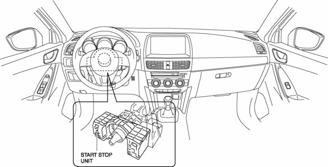
Structural view
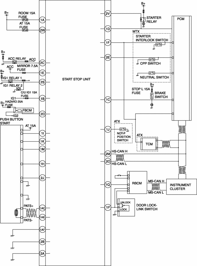
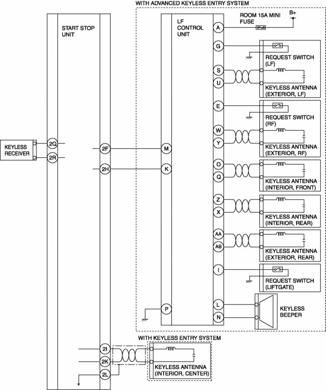
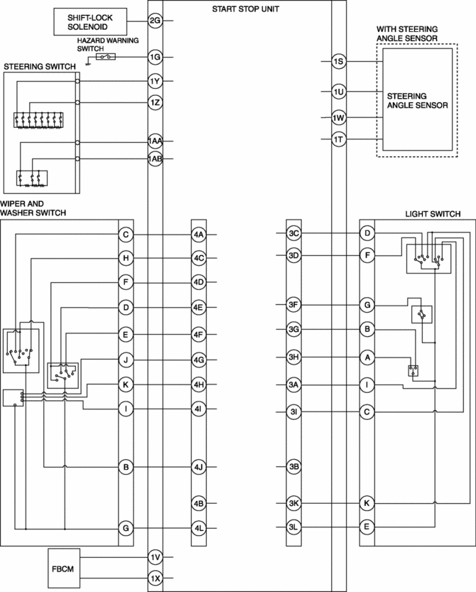
System wiring diagram
Fail-safe
Keyless entry system
-
KEY warning light (red) illuminates.
Advanced keyless entry system
-
KEY warning light (red) illuminates.
Push button start system
-
If a malfunction is detected in the push button start system, the engine can be started by pressing and holding the press button start.In addition, if the following conditions are met, engine starting is inhibited.
-
Certain period of time has elapsed since malfunction is detected in push button start
-
Engine is started a certain number of times by pressing and holding push button start
-
Flashes the push button start indicator light (amber).
Immobilizer system
-
Flashes the push button start indicator light (amber).
 Side Air Bag Sensor [Standard Deployment Control System]
Purpose
The side air bag sensor detects an impact during a lateral collision.
Function
The side air bag sensor converts the detected impact to an electrical signal.
Construct ...
 Start Stop Unit Configuration (Using As Built Data)
NOTE:
If the configuration is performed using As-Built data, the set value of the
personalization function is reset to the initial value (condition when shipped
from factory). Verify the ...
Other materials:
Turn And Hazard Indicator Alarm
Purpose
The turn and hazard indicator alarm notifies the driver that a turn light
or the hazard warning lights are flashing.
Function
When the instrument cluster receives the turn signal/hazard warning indicator
light illumination request signal sent from the front body con ...
Wheel Hub Component Removal/Installation [Awd]
CAUTION:
Performing the following procedures without first removing the ABS wheel-speed
sensor may possibly cause an open circuit in the wiring harness if it is pulled
by mistake. Before performing the following procedures, disconnect the ABS wheel-speed
sensor connector (body sid ...
Fuel Filler Lid Opener Cable Removal/Installation
1. Disconnect the negative battery cable..
2. Remove the following parts:
a. Front scuff plate (LH).
b. Front seat (LH).
c. Rear scuff plate.
d. B-pillar lower trim (LH).
e. Rear seat (4:2:4 split type).
f. Rear seat cushion (6:4 split type).
g. Rear seat back (6:4 split type).
h. ...
