Mazda CX-5 Service & Repair Manual: Climate Control Unit Inspection [Full Auto Air Conditioner]
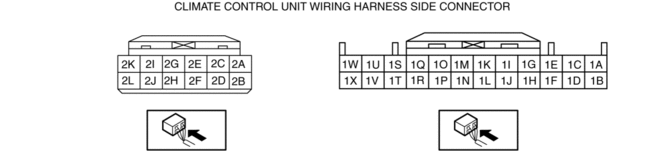
1. Remove the climate control unit with the connector connected..
2. Switch the ignition ON (engine off or on).
3. Connect the negative (-) lead of the tester to body ground.
4. By inserting the positive (+) lead of the tester into each climate control unit terminal, measure the voltage according to the terminal voltage table.
-
If there is any malfunction, inspect the parts under “Inspection item (s)”.
-
If the parts under “Inspection item (s)” are found to be normal (except for terminal 2D), replace the climate control unit.
-
For terminal 2D, first try replacing the power MOS FET. If there is still any malfunction, replace the climate control unit.
Terminal Voltage Table (Reference)
|
Terminal |
Signal name |
Connected to |
Measurement condition |
Voltage (V) |
Inspection item (s) |
|
1A |
— |
— |
— |
— |
— |
|
1B |
— |
— |
— |
— |
— |
|
1C*1 |
Seat warmer switch signal |
Seat warmer control unit |
Because this terminal is for communication, good/no good judgment by terminal voltage is not possible. |
|
|
|
1D |
— |
— |
— |
— |
— |
|
1E |
B+ |
ROOM 15 A fuse |
Under any condition |
B+ |
|
|
1F |
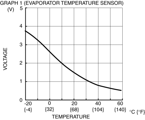
Evaporator temperature sensor input |
Evaporator temperature sensor |
Compared with temperature detected by evaporator temperature sensor |
Refer to graph 1 |
|
|
1G |
IG1 |
C/U IG1 15 A fuse |
Switch the ignition to ON |
B+ |
|
|
Switch the ignition off |
1.0 or less |
||||
|
1H |
+5V |
|
Under any condition |
5 |
|
|
1I |
— |
— |
— |
— |
— |
|
1J |
Passenger compartment temperature sensor input |
Passenger compartment temperature sensor |
Compared with temperature detected by passenger compartment temperature sensor |
Refer to graph 2 |
|
|
1K |
— |
— |
— |
— |
— |
|
1L |
— |
— |
— |
— |
— |
|
1M |
— |
— |
— |
— |
— |
|
1N |
Potentiometer input |
Driver-side air mix actuator |
Set temperature at MAX HOT |
4.3 or more |
|
|
Set temperature at MAX COLD |
1.0 or less |
||||
|
1O |
— |
— |
— |
— |
— |
|
1P |
Potentiometer input |
Passenger-side air mix actuator |
Set temperature at MAX HOT |
4.3 or more |
|
|
Set temperature at MAX COLD |
1.0 or less |
||||
|
1Q |
— |
— |
— |
— |
— |
|
1R |
Potentiometer input |
Airflow mode actuator |
VENT |
4.3 or more |
|
|
BI-LEVEL |
3.4 |
||||
|
HEAT |
2.5 |
||||
|
HEAT/DEF |
1.6 |
||||
|
DEFROSTER |
0.7 or less |
||||
|
1S |
MS_CAN_H |
CAN related module |
Because this terminal is for communication, good/no good judgment by terminal voltage is not possible. |
|
|
|
1T |
Solar radiation sensor (RH) input |
Solar radiation sensor |
Sunlight shined directly on the solar radiation sensor |
4 |
|
|
Blocking light to solar radiation sensor |
1.0 or less |
||||
|
1U |
MS_CAN_L |
CAN related module |
Because this terminal is for communication, good/no good judgment by terminal voltage is not possible. |
|
|
|
1V |
Solar radiation sensor (LH) input |
Solar radiation sensor |
Sunlight shined directly on the solar radiation sensor |
4 |
|
|
Blocking light to solar radiation sensor |
1.0 or less |
||||
|
1W |
GND |
Body ground |
Under any condition |
1.0 or less |
|
|
1X |
Sensor GND |
|
Under any condition |
1.0 or less |
|
|
2A |
Blower motor feedback |
|
Fan stopped |
B+ |
|
|
Fan: manual 1st |
10.33 |
||||
|
Fan: manual 7th |
0.4 or less |
||||
|
2B |
— |
— |
— |
— |
— |
|
2C |
IG2 |
Front body control module (FBCM) |
Switch the ignition ON (engine off or on) |
B+ |
|
|
Switch the ignition off |
1.0 or less |
||||
|
2D |
Blower fan speed control |
Power MOS FET |
Fan stopped |
1.0 or less |
|
|
Fan: manual 1st |
2.2 |
||||
|
Fan: manual 7th |
9.7 |
||||
|
2E |
Motor operation (HOT) |
Driver-side air mix actuator |
Moving towards HOT |
B+ |
|
|
Moving towards COLD |
1.0 or less |
||||
|
2F |
Motor operation (HOT) |
Passenger-side air mix actuator |
Moving towards HOT |
B+ |
|
|
Moving towards COLD |
1.0 or less |
||||
|
2G |
Motor operation (COLD) |
Driver-side air mix actuator |
Moving towards HOT |
1.0 or less |
|
|
Moving towards COLD |
B+ |
||||
|
2H |
Motor operation (COLD) |
Passenger-side air mix actuator |
Moving towards HOT |
1.0 or less |
|
|
Moving towards COLD |
B+ |
||||
|
2I |
Motor operation (VENT) |
Airflow mode actuator |
Moving towards VENT |
B+ |
|
|
Moving towards DEFROSTER |
1.0 or less |
||||
|
2J |
Motor operation (FRESH) |
Air intake actuator |
Moving towards RECIRCULATE |
1.0 or less |
|
|
Moving towards FRESH |
B+ |
||||
|
2K |
Motor operation (DEFROSTER) |
Airflow mode actuator |
Moving towards DEFROSTER |
B+ |
|
|
Moving towards VENT |
1.0 or less |
||||
|
2L |
Motor operation (RECIRCULATE) |
Air intake actuator |
Moving towards RECIRCULATE |
B+ |
|
|
Moving towards FRESH |
1.0 or less |
||||
*1 With seat warmer.
|
|
|

 Climate Control Unit Disassembly/Assembly [Manual Air Conditioner]
1. Disassemble in the order indicated in the figure.
1
Dial
2
Airflow mode wire
(See Wire Removal Note.)
(See Wire Installation Note.)
...
 Climate Control Unit Inspection [Manual Air Conditioner]
1. Remove the climate control unit with the connector connected..
2. Switch the ignition ON (engine off or on).
3. Connect the negative (-) lead of the tester to the body ground.
4. By inserting ...
Other materials:
Ignition Coil/Ion Sensor Removal/Installation [Skyactiv G 2.0]
1. Disconnect the negative battery cable..
2. Remove the plug hole plate..
3. Remove in the order indicated in the table.
4. Install in the reverse order of removal.
1
Connector
2
Ignition coil
...
Repairable Range Of Polypropylene Bumpers [Plastic Body Parts]
The three types of damaged bumpers shown below are considered repairable. Although
a bumper which has been damaged greater than this could also be repaired, it should
be replaced with a new one because such repair would detract from the looks and
quality of the bumper. In addition, such repair ...
Propeller Shaft Removal/Installation
CAUTION:
If the constant velocity joint is bent during propeller shaft removal/installation
or transportation after servicing, the constant velocity joint boot may contact
the metallic cover and the boot may be damaged. Insert a rag between the boot
and the metallic cover before ser ...
