Mazda CX-5 Service & Repair Manual: Shroud Side Member Removal [Panel Replacement]
Symbol Mark
Removal Procedure
1. Drill the 3 locations indicated by (A) shown in the figure.
2. Drill the 8 locations indicated by (B) and 2 locations indicated by (C) shown in the figure.
NOTE:
-
When drilling the 3 locations indicated by (A) and 2 locations indicated by (C) shown in the figure, do not drill a hole all the way through or there could be a problem when installing the new part.
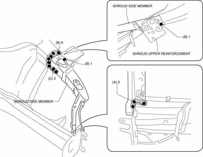
3. Remove the shroud side member.
 Shroud Side Member Installation [Panel Replacement]
Symbol Mark
Installation Procedure
1. When installing new parts, measure and adjust the body as necessary to conform
with standard dimensions.
2. Drill holes for the plug welding before inst ...
 Shroud Upper Member Removal/Installation
1. Disconnect the negative battery cable..
2. Remove the following parts:
a. Seal board upper.
b. Front bumper.
c. Front combination light.
3. Remove bolts.
4. Remove the shroud upper ...
Other materials:
Relay And Fuse Block Disassembly/Assembly
1. Insert a tape-wrapped flathead screwdriver into the service hole in the position
shown in the figure.
2. Move the flathead screwdriver in the direction of the arrow (1) shown in the
figure, pull up relay and fuse block No.1 in the direction of the arrow (2) shown
in the figure, and de ...
Dynamic Stability Control (DSC)
Outline
Electrical brake assist control has been adopted, improving safety.
The DSC HU/CM, integrating both the hydraulic unit (HU) and control module
(CM), has been adopted, resulting in a size and weight reduction.
An enhanced malfunction diagnosis system, used with the M ...
Washer Nozzle
Purpose
The washer nozzle sprays the washer fluid sent from the washer motor to the
optimum positions on the windshield.
Construction
A ball-shaped spray orifice is set inside the washer nozzle which can be
adjusted up or down.
The washer nozzle is moved u ...
