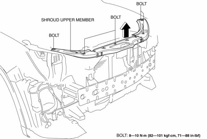
Mazda CX-5 Service & Repair Manual: Shroud Upper Member Removal/Installation
1. Disconnect the negative battery cable..
2. Remove the following parts:
a. Seal board upper.
b. Front bumper.
c. Front combination light.
3. Remove bolts.

4. Remove the shroud upper member in the direction of the arrow shown in the figure.
5. Install in the reverse order of removal.
 Shroud Side Member Removal [Panel Replacement]
Symbol Mark
Removal Procedure
1. Drill the 3 locations indicated by (A) shown in the figure.
2. Drill the 8 locations indicated by (B) and 2 locations indicated by (C) shown
in the figure.
...
 Shroud Upper Reinforcement Installation [Panel Replacement]
Symbol Mark
Installation Procedure
1. When installing new parts, measure and adjust the body as necessary to conform
with standard dimensions.
2. Drill holes for the plug welding before inst ...
Other materials:
Air Bag System Service Warnings [Standard Deployment Control System]
Air Bag Module Inspection
Inspecting an air bag module using a tester can operate (deploy) the air
bag module, which may cause serious injury. Do not use a tester to inspect an
air bag module. Always use the on-board diagnostic function to diagnose the
air bag module for malfunctions ...
Seat Belt
Fastening the Seat Belt
Position the lap belt as low as possible, not on the abdominal area, then adjust
the shoulder belt so that it fits snugly against your body.
Unfastening the Seat Belt
Depress the button on the seat belt buckle.
If the belt does not fully retract, pull it out and che ...
Fuel Filter (High Pressure) Removal/Installation
WARNING:
Fuel is very flammable liquid. If fuel spills or leaks from the pressurized
fuel system, it will cause serious injury or death and facility breakage. Fuel
can also irritate skin and eyes. To prevent this, always complete the “Fuel
Line Safety Procedure”, while referring ...
