Mazda CX-5 Service & Repair Manual: Shift Control Module Removal/Installation [C66 M R]
Removal
1. Shift the shift lever to the neutral position.
2. Remove the plug hole plate..
3. Disconnect the negative battery cable..
4. Remove the air cleaner and air hose as a single unit..
5. Remove the battery and battery tray..
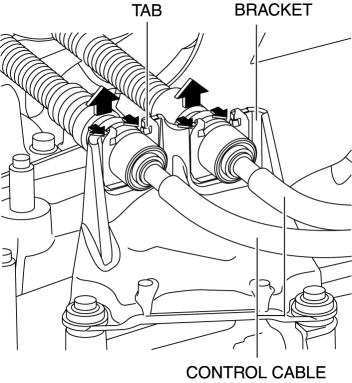
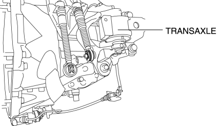
6. Disconnect the control cable from the transaxle.
a. Pull the lock pin in the direction of the arrow shown in the figure and release the control cable end lock.
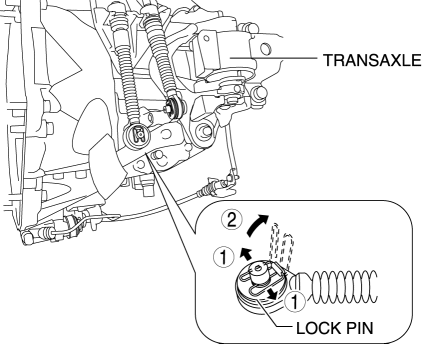
b. Press the tabs on the control cable and disconnect the control cable from the bracket on the transaxle.
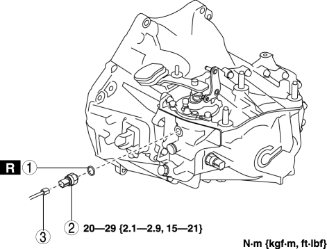
7. Remove the neutral switch in the order shown in the figure
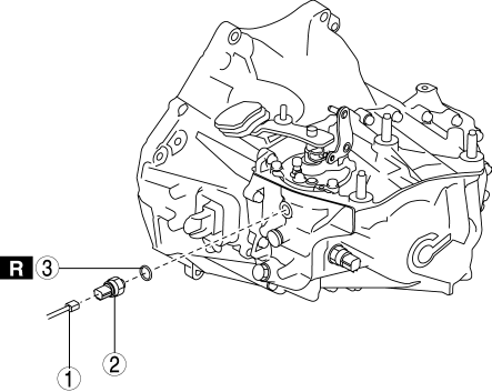
|
1 |
Connector |
|
2 |
Neutral switch |
|
3 |
Gasket |
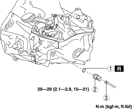
8. Remove the detent ball pin in the order shown in the figure
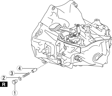
|
1 |
Plug |
|
2 |
Gasket |
|
3 |
Spring |
|
4 |
Detent ball pin |
9. Remove the back-up light switch in the order shown in the figure
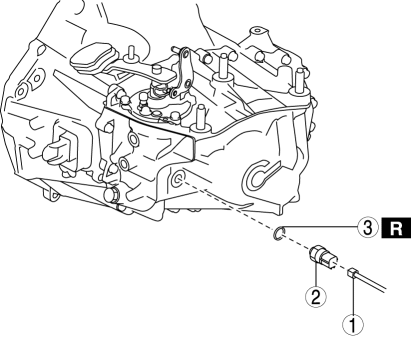
|
1 |
Connector |
|
2 |
Back-up light switch |
|
3 |
Gasket |
10. Remove the shift control module in the order shown in the figure
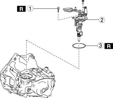
|
1 |
Breather |
|
2 |
Shift control module |
|
3 |
O-ring |
Installation
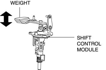
1. Verify that the shift control module is in the neutral position.
NOTE:
-
If the shift control module is in the neutral position, the shift lever with the weight can be moved up and down to a large extent.
2. Install the shift control module in the order shown in the figure
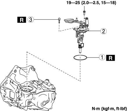
|
1 |
O-ring |
|
2 |
Shift control module |
|
3 |
Breather |
3. Install the back-up light switch in the order shown in the figure
|
1 |
Gasket |
|
2 |
Back-up light switch |
|
3 |
Connector |
4. Install the detent ball pin in the order shown in the figure
|
1 |
Detent ball pin |
|
2 |
Spring |
|
3 |
Gasket |
|
4 |
Plug |
5. Install the neutral switch in the order shown in the figure
|
1 |
Gasket |
|
2 |
Neutral switch |
|
3 |
Connector |
6. Connect the control cable to the transaxle.
7. Make sure that the shift lever can be shifted smoothly.
8. Install the battery tray and battery..
9. Install the air cleaner and air hose as a single unit..
10. Connect the negative battery cable..
11. Install the plug hole plate..
 Shift And Select Mechanism [C66 M R]
Purpose, Function
The shift and select mechanism moves the shift fork to change gears according
to the operation of the shift lever in the cabin.
Construction
Shift control module ...
 Synchronizer Mechanism [C66 M R]
Purpose, Function
For smooth gear changes, the synchronizer mechanism synchronizes the rotation
of the engaging area and engages gears.
Construction
Detent ball-type synchronizer ...
Other materials:
Fuel Gauge Sender Unit Inspection [Awd]
Fuel gauge sender unit (main)
NOTE:
For the fuel gauge sender unit removal/installation, refer to the fuel pump
removal/installation because the fuel gauge sender unit is integrated with the
fuel pump..
1. Verify that the resistance at fuel gauge sender unit (main) terminals D a ...
Liftgate Hinge Removal/Installation
1. Disconnect the negative battery cable..
2. Remove the following parts:
a. Rear scuff plate.
b. Trunk end trim.
c. Trunk side trim.
d. C-pillar trim.
e. D-pillar trim.
f. Liftgate.
3. Remove fasteners.
4. While partially peeling back the rear part of the headliner, remove nut ...
Hydraulic Lash Adjuster, Rocker Arm
Purpose, Function
HLA
The HLA maintains the valve clearance at a constant 0 mm and maintenance-free
valve clearance is realized.
Rocker arm
With the adoption of the needle roller bearing built into the rocker arm,
the contact to the cam employs rolling contact to reduce sl ...
