
Mazda CX-5 Service & Repair Manual: Rear Side Frame Installation [Panel Replacement]
Symbol Mark

Installation Procedure
1. When installing new parts, measure and adjust the body as necessary to conform with standard dimensions.
2. Drill holes for the plug welding before installing the new parts.
3. After temporarily installing new parts, make sure the related parts fit properly.
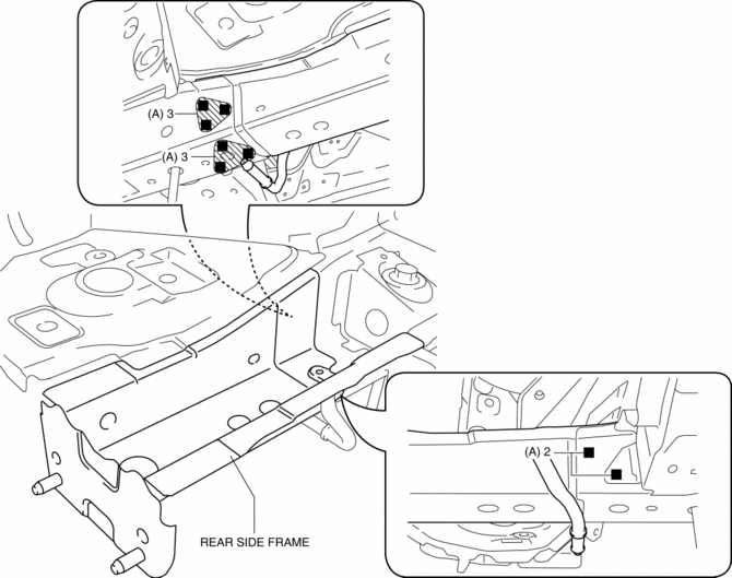
4. Plug weld the 8 locations indicated by (A) shown in the figure, then install the rear side frame.
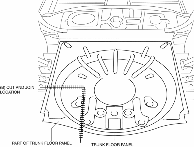
5. Cut and join the area location indicated by (B) shown in the figure.
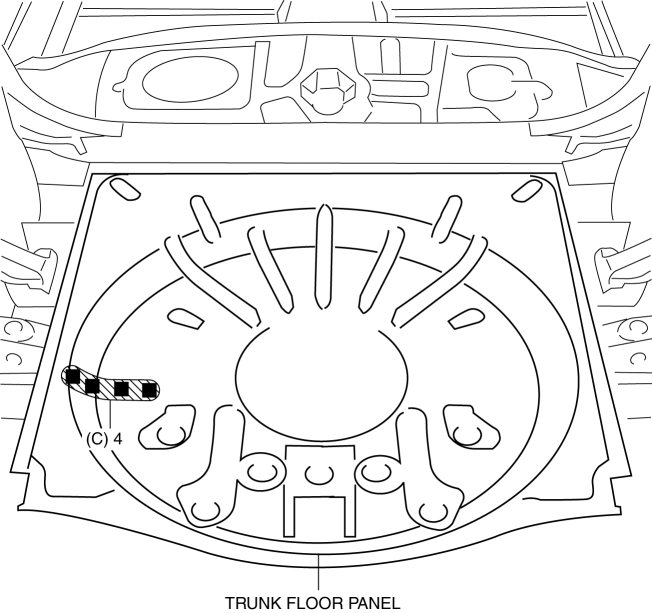
6. Plug weld the 4 locations indicated by (C) shown in the figure, then install the part of trunk floor panel.
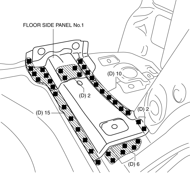
7. Plug weld the 35 locations indicated by (D) shown in the figure, then install the floor side panel No.2.
 Rear Seat Back Frame Removal/Installation
CAUTION:
When performing the procedure with a rear seat removed from the vehicle,
perform the procedure on a clean cloth so as not to damage or soil the seat.
6:4 Split Type
1. Remov ...
 Rear Side Frame Removal [Panel Replacement]
Symbol Mark
Removal Procedure
NOTE:
When drilling the 35 locations indicated by (A) and 4 locations indicated
by (C) shown in the figure, do not drill a hole all the way through or th ...
Other materials:
Camshaft Position (CMP) Sensor Inspection
Intake CMP Sensor
Visual inspection
CAUTION:
When replacing the CMP sensor, make sure there is no foreign material on
it such as metal shavings. If it is installed with foreign material, the sensor
output signal will malfunction resulting from fluctuation in magnetic flux and
caus ...
Rear Bumper Reinforcement Removal/Installation
1. Disconnect the negative battery cable..
2. Remove the following parts:
a. Rear splash shield.
b. Rear combination light.
c. Rear bumper.
3. Remove the hanger rubber in the direction of the arrow (1) shown in the figure.
4. Remove nuts.
CAUTION:
Removing the rear bumper ...
Electric Variable Valve Timing Motor/Driver Removal/Installation
WARNING:
A hot engine can cause severe burns. Turn off the engine and wait until it
is cool before servicing.
CAUTION:
Applying excessive force (force of 100 N {10.2 kgf, 22.5 lbf} or more) to
the electric variable valve timing motor/driver may cause a malfunction. When
...
