Mazda CX-5 Service & Repair Manual: Rear Sash Molding Installation
WARNING:
-
Using a utility knife with bare hands can cause injury. Always wear gloves when using a utility knife.
NOTE:
-
Double-sided adhesive tape has already been attached to the new rear sash molding.
1. When installing a new rear sash molding, follow the procedure below:
a. Carefully remove the adhesive remaining on the body using a razor blade.
b. Remove any grease or dirt from the adhesion surface of the body.
2. Remove the adhesive remaining on the rear sash molding and the body using a razor blade.
a. Remove any grease or dirt from the adhesion surface of the rear sash molding and the body.
b. Apply primer to the bonding area of the rear sash molding.
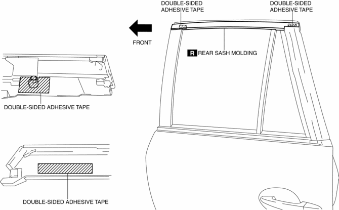
c. Affix double-sided adhesive tape to the rear sash molding as shown in the figure.

NOTE:
-
As for the double-sided adhesive tape, use 3M GT7120 or equivalent.
3. Peel off the backing of the double-sided adhesive tape.
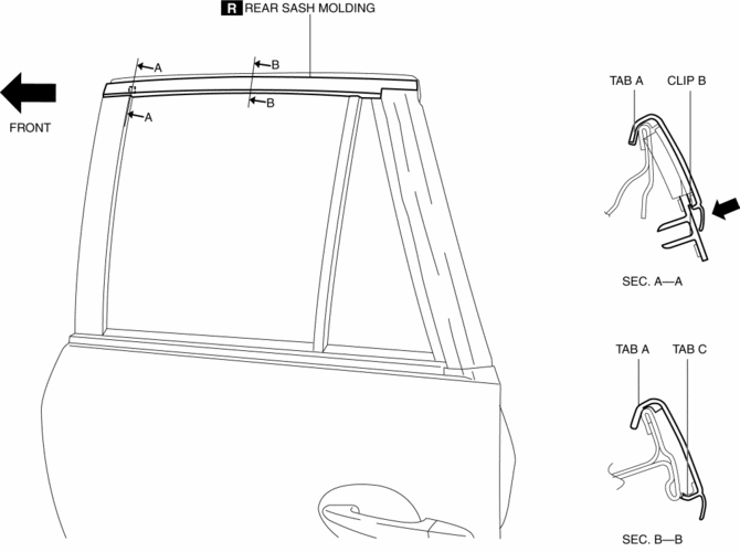
4. Hook tab A to the body in the position where clip B aligns with the sash holes.

5. Press the rear sash molding in the direction of the arrow and install clip B to the body.
CAUTION:
-
Do not press the rear sash molding in any place other than the rubber areas.
6. Press the rear sash molding from the vehicle front in the direction of the arrow and install tab C.
NOTE:
-
After installing the rear sash molding, verify that tabs A and C are connected properly to the body.
 Rear Over Fender Removal/Installation
1. Remove fasteners A.
2. Pull the rear over fender in the direction of the arrow while removing clips
B.
3. Install in the reverse order of removal. ...
 Rear Sash Molding Removal
WARNING:
Using a utility knife with bare hands can cause injury. Always wear gloves
when using a utility knife.
1. Remove the rear door garnish. (rear side).
2. Remove the double-si ...
Other materials:
Seat Warmer System
Purpose
The seat warmer system warms the front seat cushion and front seat back using
the seat warmer unit.
Function
The seat warmer unit warms the seat cushion and seat back by supplying power
to the built-in filaments.
The seat warmer unit can adjust the tempe ...
Audio Pilot®2 Microphone Removal/Installation
NOTE:
AudioPilot®2 is a registered trademark of Bose® Corporation.
1. Disconnect the negative battery cable..
2. Remove the following parts:
a. Driver-side front scuff plate.
b. Driver-side front side trim.
c. Switch panel.
d. Decoration panel.
e. Shift lever knob (MTX). ...
Supplier Identification Procedure [Audio]
NOTE:
The unit supplier can vary. When asking the supplier (service center) for
repair or replacement, identify the supplier and fill in the Audio Repair Order
Form using the following procedures.
Verification procedure using label or inscribed lettering
1. Disconnect the negati ...
