Mazda CX-5 Service & Repair Manual: Rear End Panel Removal [Panel Replacement]
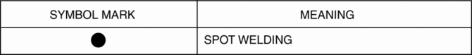
Symbol Mark
Removal Procedure
1. Drill the 77 locations indicated by (A) shown in the figure.
2. Drill the 18 locations indicated by (B) from room side shown in the figure.
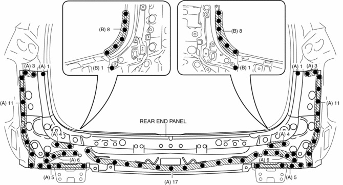
3. Remove the rear end panel.
 Rear End Panel Installation [Panel Replacement]
Symbol Mark
Installation Procedure
1. When installing new parts, measure and adjust the body as necessary to conform
with standard dimensions.
2. Drill holes for the plug welding before inst ...
 Rear Fender Lower Panel Installation [Panel Replacement]
Symbol Mark
Installation Procedure
1. When installing new parts, measure and adjust the body as necessary to conform
with standard dimensions.
2. After temporarily installing new parts, make ...
Other materials:
Tire Maintenance
Improper or inadequate vehicle maintenance can cause tires to wear abnormally.
Here are some important maintenance points:
Tire Inflation Pressure
Inspect all tire pressure monthly (including the spare) when the tires are cold.
Maintain recommended pressures for the best ride, top handling, an ...
Rear Scuff Plate Removal/Installation
1. Take the shaded area shown in the figure, detach tab A while pulling the rear
scuff plate in the direction of the arrow (1) shown in the figure, then detach hook
B, clips C, pins D while pulling in the direction of the arrow (2).
2. Take the shaded area shown in the figure, detach tab E whi ...
DSC HU/CM Inspection
1. Disconnect the DSC HU/CM connector..
2. Connect the negative battery cable..
3. Attach the tester lead to the DSC HU/CM wiring harness-side connector and
inspect voltage, continuity, or resistance according to the standard (reference)
on the table.
Standard (Reference)
...
