
Mazda CX-5 Service & Repair Manual: Rear ABS Wheel Speed Sensor Inspection [2 Wd]
Installation Visual Inspection
1. Inspect the following items:
-
If there is any malfunction, replace the applicable part.
a. Excessive play of the ABS wheel-speed sensor
b. Deformation of the ABS wheel-speed sensor
Clearance Inspection
1. Remove the ABS wheel-speed sensor.
2. Measure the distance between the ABS wheel-speed sensor installation surface and the ABS sensor rotor. This is dimension A.
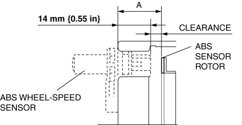
3. Calculate the clearance between the front ABS wheel-speed sensor and the ABS sensor rotor using the following formula:
-
Clearance (mm {in}) = A-14 {0.55}
4. Verify that the clearance between the ABS sensor rotor and the ABS wheel-speed sensor is as indicated below.
-
If there is any malfunction, replace it.
-
Clearance
-
0.28—1.17 mm {0.012—0.046 in}
Sensor Output Value Inspection
1. Switch the ignition to off.
2. Connect the M-MDS to the DLC-2.
3. Select the following PIDs using the M-MDS:
-
WSPD_SEN_LR (LR ABS wheel-speed sensor)
-
WSPD_SEN_RR (RR ABS wheel-speed sensor)
4. Start the engine and drive the vehicle.
5. Verify that the display of the M-MDS shows the same value as the speedometer.
-
If there is any malfunction, replace the ABS wheel-speed sensor.
 Front ABS Wheel Speed Sensor Removal/Installation
1. Remove the mudguard..
2. Remove in the order indicated in the table.
3. Install in the reverse order of removal.
4. After installation, verify that there is no twisting in the front ABS wheel ...
 Rear ABS Wheel Speed Sensor Inspection [Awd]
Installation Visual Inspection
1. Inspect the following items:
If there is any malfunction, replace the applicable part.
a. Excessive play of the ABS wheel-speed sensor
b. Deformation ...
Other materials:
Compression Inspection
WARNING:
Hot engines and oil can cause severe burns. Be careful not to burn yourself
during removal/installation of each component.
Fuel vapor is hazardous. It can very easily ignite, causing serious injury
and damage. Always keep sparks and flames away from fuel.
Fuel ...
Front Brake (Disc)
Purpose/Function
Large diameter, ventilated disc type front brakes with a 297 mm {11.7 in}
diameter and 28 mm {1.1 in} thickness have been adopted, improving braking force
and fade resistance.
Construction
Operation
When brake fluid is applied, the piston equipped on o ...
Main Fuse Removal/Installation
1. Disconnect the negative battery cable..
2. Insert a tape-wrapped flathead screwdriver into the service hole in the position
shown in the figure.
3. Move the flathead screwdriver in the direction of the arrow (1) shown in the
figure, pull up the main fuse cover in the direction of the ...
