Mazda CX-5 Service & Repair Manual: Blind Spot Monitoring (Bsm) System
Outline
-
The blind spot monitoring (BSM) system detects vehicles approaching from the rear blind spots, and illuminates the BSM indicator light on the outer mirror glass. When the BSM indicator light is illuminated and the turn light switch is turned on to the side in which the indicator light is illuminated, the indicator light flashes and a warning alarm is activated to alert the driver.
-
The BSM system operates while the vehicle is traveling at approx. 32 km/h {20 mph} or more
.
-
The BSM system has an on-board diagnostic function for improved serviceability.
WARNING:
-
The BSM system is not a substitute for the driver in confirming safety. The driver is responsible for assuring the safety of lane changes and other maneuvers. Do not rely completely on the BSM system and always confirm the safety around the vehicle visually before changing lanes.
-
Because the BSM system has various restrictions in the operation, the BSM indicator light might not illuminate or it may be delayed even if there is a vehicle traveling in the adjacent lane.
-
If there is mud, water, or snow adhering to the areas near the BSM control module, obstruction of the radar could result in the system not appropriately detecting a target vehicle, or complete non-detection of the target vehicle. Always pay attention to the direction of vehicle travel and the area around the vehicle.
-
Do not block the area around the BSM control module on the rear bumper with foreign material (such as bumper stickers) so as not to affect the BSM system functions.
-
Perform radar aiming for the BSM control module if the rear bumper has received an impact.
-
The BSM system may not operate normally under the following conditions:
-
Dirt, ice or snow is adhering to the rear bumper surface.
-
The vehicle is driven in heavy rain or snowfall, or under conditions where water on the road is sprayed by the vehicle.
-
The vehicle is towing a trailer.
-
The vehicle accelerates from a standing-start with a target vehicle alongside.
-
A target vehicle moves laterally from a lane two lanes over to the adjacent lane.
-
The difference in vehicle speed between the vehicle and a target vehicle is higher with the target vehicle passing through the detection area in a very short period.
-
On a steep incline, or if there is a difference in height between lanes.
-
The BSM system may detect guardrails or parked vehicles on a road shoulder and activate the warning light/beep.
-
The BSM control module may not detect all types of vehicles. In particular, detection of the following types of vehicles may not occur:
-
A vehicle driving at a low speed
-
Small vehicles such as motorcycles
-
Vehicles with body shapes that may not reflect radar such as unloaded trailers
-
Vehicles with low vehicle height
-
The difference in vehicle speed between the vehicle and a target vehicle is extremely high.
-
A target vehicle accelerates suddenly from the rear of the vehicle and changes to the adjacent lane.
-
A target vehicle which is traveling in the vehicle's blind spot at nearly the same speed for long periods
-
The BSM indicator light may be difficult to view under the following conditions:
-
Sunlight at sunrise and sunset is reflected in and around the BSM indicator light
-
A lighting device with strong illumination is used in the vehicle
-
On a road with a narrower lane width, the system could detect vehicles on a lane next to the adjacent lane and cause the warning light/beep to operate. Conversely, on a road with a wider lane width, the system may not detect vehicles on the adjacent lane and may not operate the warning light/beep.
CAUTION:
-
If the rear bumper installation position is changed or individual differences (coating film/thickness) occur, the radar angle will deviate and the BSM system may not operate properly. Perform the radar aiming using the SSTs (Service Special Tools) and Mazda Modular Diagnostic System (M-MDS) when any of the following items have been performed.
-
BSM control module is replaced
-
BSM bracket is replaced
-
Rear bumper is repaired or replaced
-
Vehicle’s rear area is repaired due to collision
-
Refer to the Workshop Manual for the radar aiming procedure.
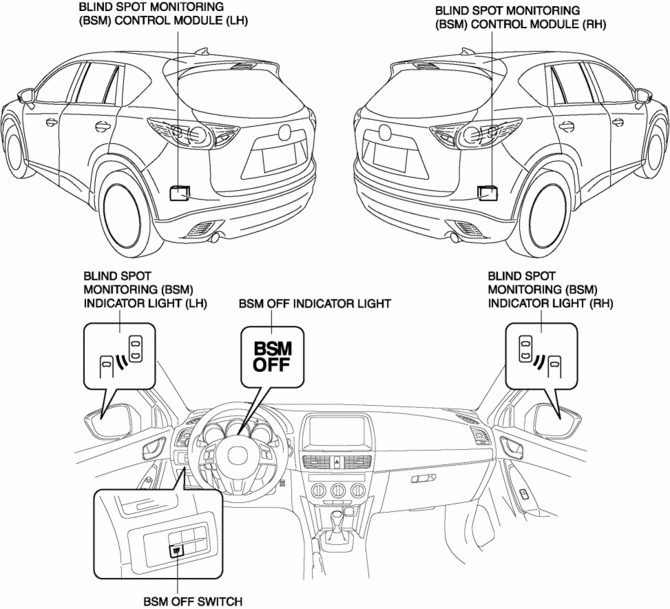
Structural view

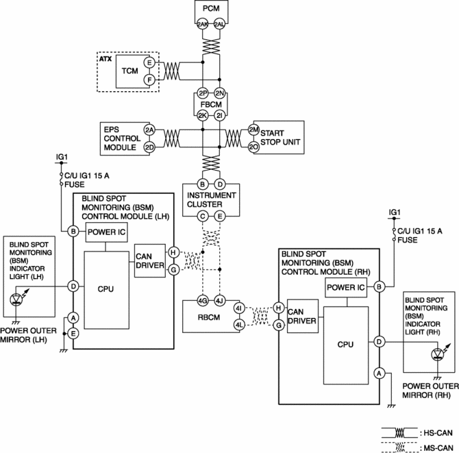
System wiring diagram

Operation
-
When the vehicle is driven at approx. 32 km/h {20 mph} or more
and a vehicle enters the radar-monitored area at the rear, the BSM indicator light illuminates. If the turn signal lever is operated to the side the BSM indicator light illuminated, the BSM indicator light starts flashing and the warning alarm operates.
-
The BSM system has operation, operation-stop, warning, and alert modes.
System operation conditions
-
The BSM can operate when the following conditions are met with the ignition switched ON.
-
Vehicle speed is approx. 32 km/h {20 mph} or more
-
Shift lever is not in reverse (MTX) (The BSM system is automatically turned off when the shift lever is in reverse.)
-
Selector lever is not in R position (ATX) (The BSM system is automatically turned off when the selector lever is in the R position.)
System turn-off procedure
-
The BSM can be turned off by pressing the BSM OFF switch with the ignition switched ON. (At this time, the BSM OFF indicator light in the instrument cluster illuminates.)
-
When the BSM OFF switch is pressed again with the system turned off, the system becomes operable and the BSM OFF indicator light in the instrument cluster turns off.
-
The BSM-OFF condition is cancelled when the ignition is switched off (LOCK or ACC), and the BSM system becomes operable automatically when the ignition is switched ON the next time.
Alert Mode
-
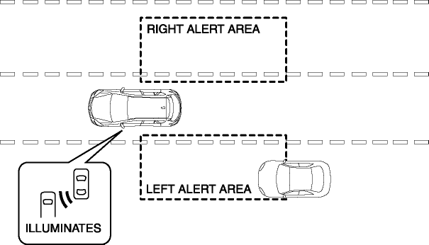
If a vehicle enters the alert area when passing or being passed, the system alerts the driver that a vehicle is in the alert area as follows:
-
If a vehicle enters the alert area on the left, the BSM indicator light (LH) in the left outer mirror illuminates.
-
If a vehicle enters the alert area on the right, the BSM indicator light (RH) in the right outer mirror illuminates.

Warning Mode
-
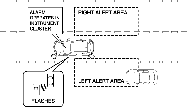
While in the alert mode, if the turn signal lever is operated to the side the target vehicle is detected, the system warns the driver of the possibility of an accident as follows:
-
BSM indicator light in the outer mirror flashes
-
Warning alarm in instrument cluster operates

 Blind Spot Monitoring (Bsm) Off Switch Inspection
1. Disconnect the negative battery cable..
2. Remove the BSM OFF switch..
3. Verify that the resistance between BSM OFF switches B and C is as indicated
in the table.
If the resistan ...
 Blind Spot Monitoring (Bsm) Warning Alarm
Purpose
The Blind Spot Monitoring (BSM) warning alarm warns the driver of a possible
accident.
Function
If the instrument cluster receives a warning sound request signal from th ...
Other materials:
Seat Warmer Switch Removal/Installation
NOTE:
The seat warmer switch are integrated into the climate control unit. (with
full-auto air conditioner system)
The seat warmer switch are integrated into the clock. (with manual air conditioner
system)
For the seat warmer switch removal/installation, refer to the cl ...
Climate Control Unit Inspection [Manual Air Conditioner]
1. Remove the climate control unit with the connector connected..
2. Switch the ignition ON (engine off or on).
3. Connect the negative (-) lead of the tester to the body ground.
4. By inserting the positive (+) lead of the tester into the climate control
unit connector, measure the voltage ...
Column Cover Removal/Installation
1. Pull down the steering wheel.
2. Press the shaded area shown in the figure using your thumb, and lift the upper
column cover in the direction of arrow (1).
3. Pull the upper column cover in the direction of the arrow (2) and remove it
while detaching pins A, tabs B and guides C.
4. ...
