Mazda CX-5 Service & Repair Manual: Outer Mirror Glass Removal
1. Disconnect the negative battery cable..
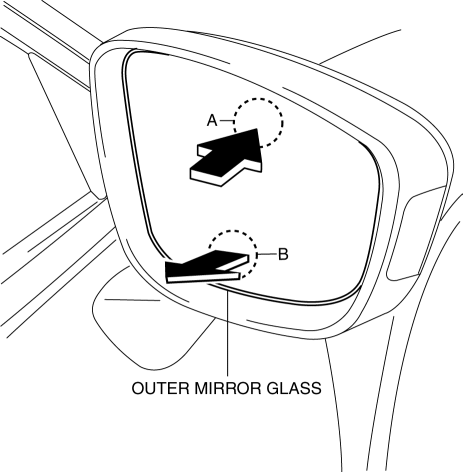
2. Press area A of the outer mirror glass shown in the figure so that area B moves outward.
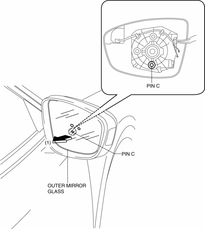
3. Put your hand on the lower part of the outer mirror glass and while supporting the hatch-marked area shown in the figure, remove pin C in the direction of the arrow (1).
CAUTION:
-
When removing the outer mirror glass, if excessive force is applied to the area other than cross-hatched area, the outer mirror glass could be damaged.
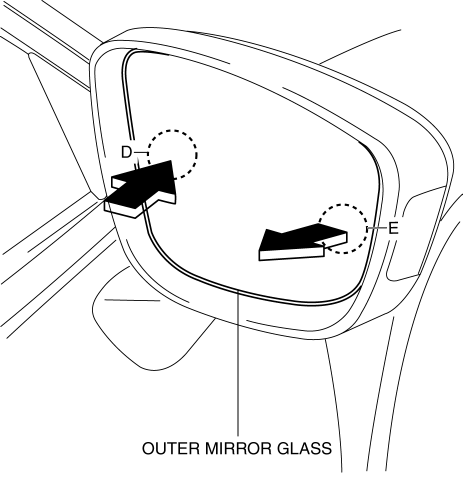
4. Press area D of the outer mirror glass shown in the figure so that area E moves outward.
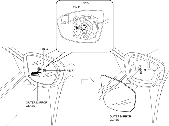
5. Put your hand on the side part of the outer mirror glass and while supporting the hatch-marked area shown in the figure, remove pin F, pin G in the direction of the arrow (2).
CAUTION:
-
When removing the outer mirror glass, if excessive force is applied to the area other than cross-hatched area, the outer mirror glass could be damaged.
6. Pull the outer mirror glass in the direction of the arrow (1) and remove it while detaching the pin E from the mirror glass holder.
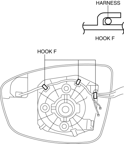
7. Remove the harness from hooks F.
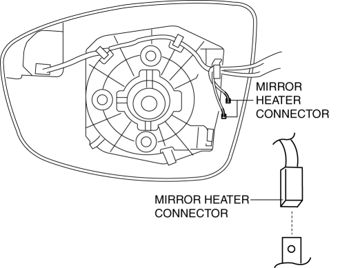
8. Disconnect the mirror heater connectors. (with heated outer mirror)
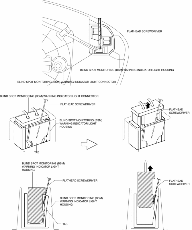
9. Insert a tape-wrapped flathead screwdriver to the position shown in the figure, remove the blind spot monitoring (BSM) warning indicator light connector (with blind spot monitoring system).
CAUTION:
-
The connector can be easily deformed, therefore do not apply excessive force.
10. Remove the mirror glass holder and the outer mirror glass as a single unit.
 Outer Mirror Glass Installation
1. Connect the mirror heater connectors. (with heated outer mirror)
2. Connect the blind spot monitoring (BSM) warning indicator light connector
(with blind spot monitoring system).
NOTE:
...
 Power Outer Mirror
Outline
The power outer mirror adjusts the outer mirror glass position up/down and
left/right using the up/down adjustment motor and, left/right adjustment motor.
The up/down adjustm ...
Other materials:
Liftgate Opener Switch Inspection
1. Disconnect the negative battery cable..
2. Remove the following parts:
a. Liftgate upper trim.
b. Liftgate side trim.
c. Liftgate lower trim.
d. Liftgate garnish.
e. Liftgate opener switch.
3. Verify the continuity of liftgate opener switch terminals B and C.
If not as i ...
Seat Track Position Sensor Removal/Installation [Two Step Deployment Control
System]
1. Switch the ignition to off.
2. Disconnect the negative battery cable and wait for 1min or more..
3. Remove the front driver’s seat..
4. Disconnect the connector from the seat track position sensor by pressing the
connector tab and pulling out the lock lever in the direction of the arro ...
Steering Gear And Linkage Removal/Installation
CAUTION:
Performing the following procedures without first removing the ABS wheel-speed
sensor may possibly cause an open circuit in the wiring harness if it is pulled
by mistake. Before performing the following procedures, disconnect the ABS wheel-speed
sensor (axle side) and fix t ...
