Mazda CX-5 Service & Repair Manual: Outer Mirror Glass Installation
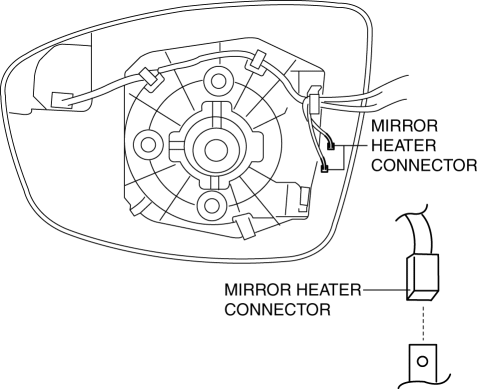
1. Connect the mirror heater connectors. (with heated outer mirror)
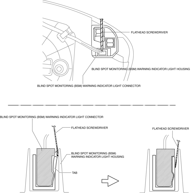
2. Connect the blind spot monitoring (BSM) warning indicator light connector (with blind spot monitoring system).
NOTE:
-
Lightly pull the blind spot monitoring (BSM) warning indicator light connector and verify that the blind spot monitoring (BSM) warning indicator light housing cannot be pulled off. If the connection is poor, insert a tape-wrapped flathead screwdriver into position A shown in the figure and engage the connector.
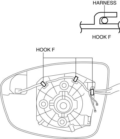
3. Install the harness from the hook.
4. Press part A on the outer mirror glass and install pin A.
CAUTION:
-
When installing the outer mirror glass, if excessive force is applied to the area other than cross-hatched area, the outer mirror glass could be damaged.
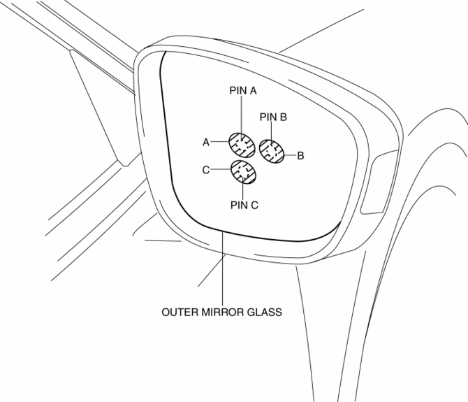
5. Press part B on the outer mirror glass and install pin B.
6. Press part C on the outer mirror glass and install pin C.
7. Connect the negative battery cable..
 Outer Mirror Glass Installation
1. Connect the mirror heater connectors. (with heated outer mirror)
2. Connect the blind spot monitoring (BSM) warning indicator light connector
(with blind spot monitoring system).
NOTE:
...
 Outer Mirror Glass Removal
1. Disconnect the negative battery cable..
2. Press area A of the outer mirror glass shown in the figure so that area B
moves outward.
3. Put your hand on the lower part of the outer mirror ...
Other materials:
Fuel Pump Relay
Purpose, Function
Controls the fuel pump on/off according to control signals from the PCM.
The fuel pump is operated only at engine start or when the engine is running
to improve safety.
Construction
The fuel pump relay is installed in the relay and fuse block.
...
Engine Coolant Temperature (ECT) Sensor Removal/Installation
WARNING:
When the engine is hot, it can badly burn. Turn off the engine and wait until
it is cool before removing the ECT sensor.
ECT Sensor No.1
1. Disconnect the negative battery cable..
2. Remove the plug hole plate..
3. Drain the engine coolant..
4. Pull out the evaporati ...
Sail Garnish Removal/Installation
1. Open the front door.
2. Affix protective tape to the position shown in the figure.
3. Insert a tape-wrapped flathead screwdriver into the shown in the figure and
remove the clip A in the direction of arrow (1).
4. Pull the sail garnish in the direction of the arrow (2) and remove it w ...
