Mazda CX-5 Service & Repair Manual: Outer Mirror Glass Installation
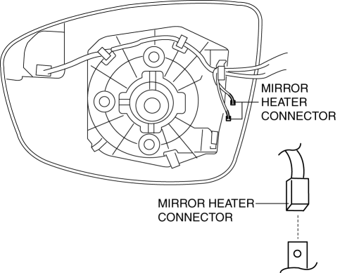
1. Connect the mirror heater connectors. (with heated outer mirror)
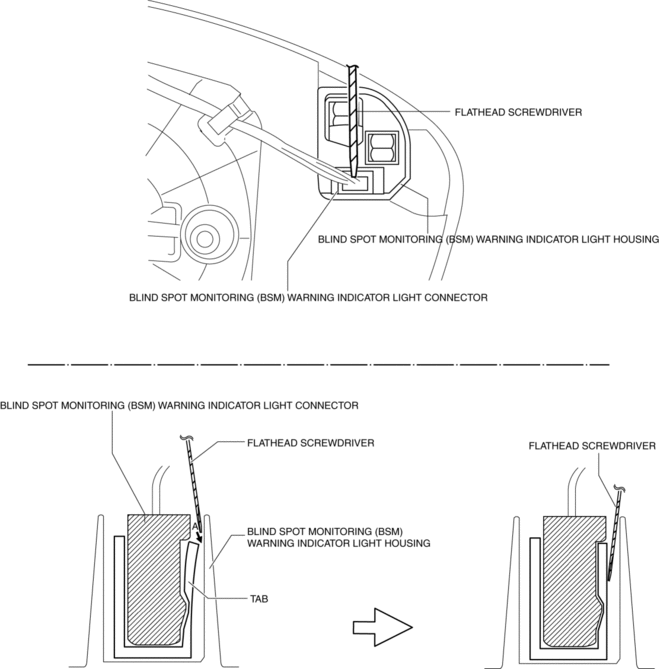
2. Connect the blind spot monitoring (BSM) warning indicator light connector (with blind spot monitoring system).
NOTE:
-
Lightly pull the blind spot monitoring (BSM) warning indicator light connector and verify that the blind spot monitoring (BSM) warning indicator light housing cannot be pulled off. If the connection is poor, insert a tape-wrapped flathead screwdriver into position A shown in the figure and engage the connector.
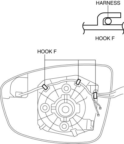
3. Install the harness from the hook.
4. Press part A on the outer mirror glass and install pin A.
CAUTION:
-
When installing the outer mirror glass, if excessive force is applied to the area other than cross-hatched area, the outer mirror glass could be damaged.
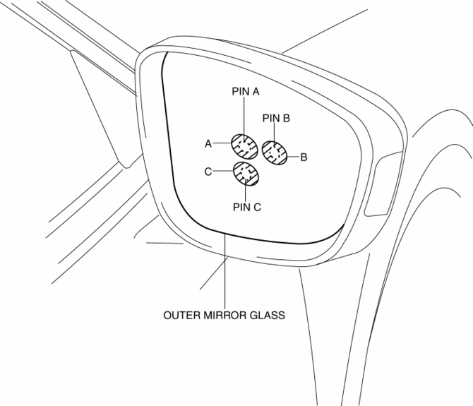
5. Press part B on the outer mirror glass and install pin B.
6. Press part C on the outer mirror glass and install pin C.
7. Connect the negative battery cable..
 Outer Mirror Glass Inspection
Heated Outer Mirror
1. Disconnect the negative battery cable..
2. Remove the outer mirror glass..
3. Verify that the resistance and continuity between the heated outer mirror
terminals is as in ...
 Outer Mirror Glass Installation
1. Connect the mirror heater connectors. (with heated outer mirror)
2. Connect the blind spot monitoring (BSM) warning indicator light connector
(with blind spot monitoring system).
NOTE:
...
Other materials:
Emission System
Purpose, Outline
A single-nano catalyst has been adopted for the under-floor, three-way catalyst
to improve emission gas purification efficiency.
Structural View
Engine compartment side
Exhaust system side
2WD
AWD
Fuel tank side
U.S.A. and CANADA (2WD)
U.S.A. a ...
Power Window Subswitch Inspection
1. Disconnect the negative battery cable..
2. Remove the power window subswitch..
3. Verify that the continuity between the power window subswitch terminals is
as indicated in the table.
If not as indicated in the table, replace the power window subswitch.
...
Exhaust System
Purpose, Outline
A 4-2-1 exhaust system has been adopted which reduces residual gas in the
cylinders using the scavenging effect and contributes to a high compression
ratio.
The loop structure of the exhaust pipes for the 4-2-1 system takes up less
space.
Structural Vie ...
