Mazda CX-5 Service & Repair Manual: Oil Pressure Switch Removal/Installation [Fw6 A EL, Fw6 Ax EL]
WARNING:
-
A hot transaxle and ATF can cause severe burns. Turn off the engine and wait until they are cool.
-
Always wear protective eye wear when using the air compressor. If the air compressor is used, any particles of dirt or soiling could spatter and get into the eyes.
CAUTION:
-
If the oil pressure switch has been replaced, perform initial learning..
-
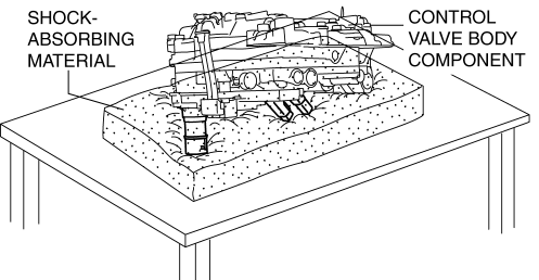
Placing the control valve body connector side pointed downward could damage the control valve body connector part or sensor. If the servicing can only be performed by pointing the control valve body connector side downward, spread shock-absorbing material, which does not produce dust or foreign matter, and place the control valve body connector part and sensor on the table so that they do not directly contact the table.
Oil Pressure Switch A
1. Select the selector lever to P position.
2. Disconnect the negative battery cable..
3. Remove the front under cover No.2..
4. Clean the transaxle exterior throughout with a steam cleaner or cleaning solvents.
5. Remove the air cleaner component..
6. Remove the control valve body..
7. Remove the oil seal (control valve body)..
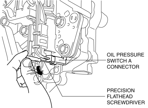
8. Insert a precision flathead screwdriver and move it in the direction of the arrow to disconnect the oil pressure switch A connector as shown in the figure.
CAUTION:
-
Do not scratch the oil pressure switch A and oil pressure switch connector A with the precision flathead screwdriver.
-
When disconnecting connectors, grasp the connectors, not the wiring harnesses. Otherwise, the wiring harnesses may be pulled out of the connector causing poor contact.
9. Remove the oil pressure switch A fitting bolts.
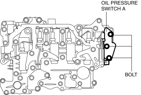
10. Detach tab shown in the figure and remove the oil pressure switch A from the control valve body.
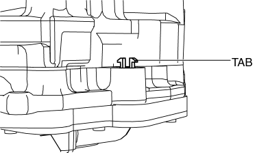
11. Install the oil pressure switch A to the control valve body.

12. Verify that the tab is attached correctly.
13. Install the oil pressure switch A fitting bolts.

-
Tightening torque
-
9—10 N·m {92—101 kgf·cm, 80—88 in·lbf}
14. Connect the oil pressure switch A connector.
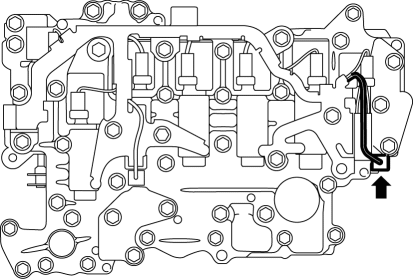
15. Install the control valve body..
16. Install the front under cover No.2..
17. Install the oil seal (control valve body)..
18. Install the hose clamp..
19. Connect the control valve body connector..
CAUTION:
-
Make sure that your hand does not touch the terminal as the connector terminal could be damaged.
-
Verify that there is no fluid or foreign matter adhering to the connector before connecting the connector.
-
Insert the connector straight as the connector terminal could be damaged.
-
Rotate the connector lever until a click is heard.
20. Add the ATF..
21. Install the air cleaner component..
22. Connect the negative battery cable..
23. Perform the “Initial Learning” (oil pressure switch A Replacement)..
24. Perform the “Mechanical System Test”..
Oil Pressure Switch B
1. Disconnect the negative battery cable..
2. Remove the front under cover No.2..
3. Clean the transaxle exterior throughout with a steam cleaner or cleaning solvents.
4. Drain the ATF..
5. Remove the oil pan.
CAUTION:
-
To avoid damaging the control valve body, if there is a large amount of foreign material at the bottom of the oil pan when the oil pan is removed, replace the oil strainer with a new one.
-
If there is not a large amount of foreign material at the bottom of the oil pan, the oil strainer does not have to be replaced.
6. Remove the oil strainer..
7. Remove the oil strainer O-ring..
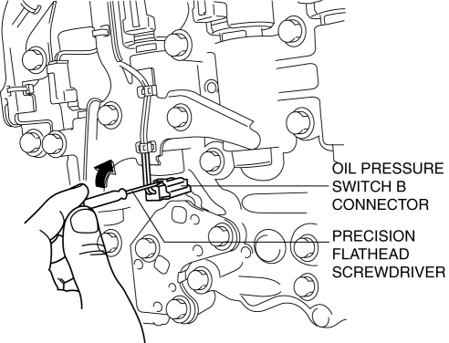
8. Insert a precision flathead screwdriver and move it in the direction of the arrow to disconnect the oil pressure switch B connector as shown in the figure.
CAUTION:
-
Do not scratch the oil pressure switch B and oil pressure switch connector B with the precision flathead screwdriver.
-
When disconnecting connectors, grasp the connectors, not the wiring harnesses. Otherwise, the wiring harnesses may be pulled out of the connector causing poor contact.
9. Remove the oil pressure switch B.
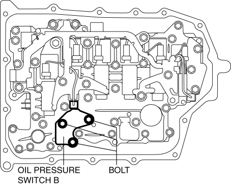
10. Install the oil pressure switch B.

-
Tightening torque
-
9—10 N·m {92—101 kgf·cm, 80—88 in·lbf}
11. Connect the oil pressure switch B connector.
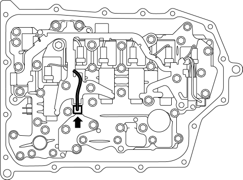
12. Install the oil strainer O-ring..
NOTE:
-
If there is a large amount of foreign material at the bottom of the oil pan, replace the oil strainer with a new one.
13. Install the oil strainer..
14. Apply a light coat of silicon sealant (TB1217E) to the contact surfaces of the oil pan and transaxle case.
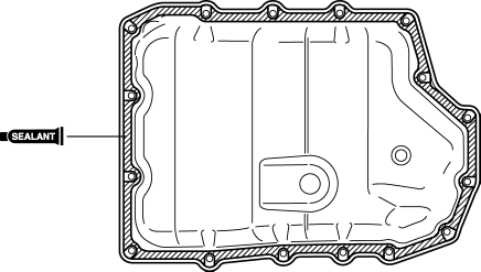
CAUTION:
-
Clean any remaining silicone sealant on the contact surface of the transaxle case and oil pan, and degrease the sealant area. Otherwise, oil could leak.
15. Install the oil pan with new bolts before the applied sealant starts to harden.
-
Tightening torque
-
8—10 N·m {82—101 kgf·cm, 71—88 in·lbf}
16. Install the front under cover No.2..
17. Add the ATF..
18. Connect the negative battery cable..
19. Perform the “Initial Learning” (oil pressure switch B Replacement)..
20. Perform the “Mechanical System Test”..
 Oil Pressure Switch Inspection
1. Switch the ignition ON (engine off) and verify that the oil pressure warning
light is illuminated.
2. Start the engine and verify that the oil pressure warning light turns off.
If the ...
 Oil Pressure Switch [Fw6 A EL, Fw6 Ax EL]
Purpose/Function
The oil pressure switch detects the engagement pressures of the low clutch,
2-6 brake, R-3-5 brake, and the high clutch.
The oil pressure switch signal is used for a ...
Other materials:
Manual Transaxle Shift Mechanism Removal/Installation [C66 M R]
1. Disconnect the negative battery cable..
2. Remove the shift lever using the following procedure:
a. Remove the upper panel..
b. Remove the shift lever knob.
c. Remove the shift panel..
d. Remove the side wall..
e. Remove the rear console..
f. Press the tabs on the control cable ...
Rear Seat Back Trim Removal/Installation
6:4 Split Type
1. Remove the trunk board..
2. Remove the rear seat back..
3. Remove the headrest.
4. Remove the rear seat back frame..
5. Remove the C rings in the order of (1), (2), (3), and (4) shown in the figure,
and remove the rear seat back trim from the rear seat back pad.
CA ...
Rear Fender Lower Panel Installation [Panel Replacement]
Symbol Mark
Installation Procedure
1. When installing new parts, measure and adjust the body as necessary to conform
with standard dimensions.
2. After temporarily installing new parts, make sure the related parts fit properly.
3. Spot weld the 26 locations shown in the figure, then ins ...
