Mazda CX-5 Service & Repair Manual: Oil Control Valve (OCV) Inspection [Skyactiv G 2.0]
Coil Resistance Inspection
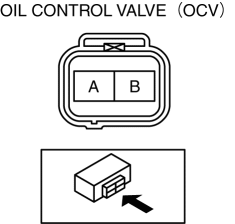
1. Disconnect the negative battery cable..
2. Remove the plug hole plate..
3. Disconnect the OCV connector.
4. Measure the resistance between terminals A and B using an ohmmeter.
-
OCV coil resistance
-
6.9—7.5 ohms [20°C {68°F}]
-
If not as specified, replace the OCV..
5. Install in the reverse order of removal.
Spool Valve Operation Inspection
1. Disconnect the negative battery cable..
2. Remove the OCV..
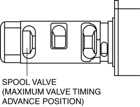
3. Verify that the spool valve in the OCV is in the maximum valve timing advance position as indicated in the figure.
-
If not as specified, replace the OCV..
4. Verify that the battery is fully charged..
-
If not as specified, recharge the battery..
NOTE:
-
When applying battery positive voltage between the OCV terminals, the connection can be either of the following:
-
Positive battery cable to terminal A, negative battery cable to terminal B
-
Positive battery cable to terminal B, negative battery cable to terminal A
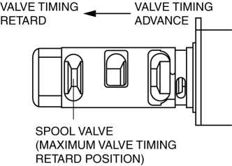
5. Apply battery positive voltage between the OCV terminals and verify that the spool valve operates and moves to the maximum valve timing retard position.
-
If not as specified, replace the OCV..
6. Stop applying battery positive voltage and verify that the spool valve returns to the maximum valve timing advance position.
-
If not as specified, replace the OCV..
7. Install the OCV..
 Eps Control Module Inspection
1. Remove the driver-side front scuff plate..
2. Remove the driver-side front side trim..
3. Remove the car-navigation unit (with car-navigation system)..
4. Remove the switch panel..
5. Remov ...
 Oil Control Valve (OCV) Removal/Installation [Skyactiv G 2.0]
WARNING:
A hot engine can cause severe burns. Turn off the engine and wait until it
is cool before servicing.
1. Disconnect the negative battery cable..
2. Remove the plug hole plat ...
Other materials:
Seat
Outline
Front seat
A manual seat or power seat has been adopted on the driver's seat.
A seat warmer system has been adopted on the front seats. (with seat warmer
system)
A manual seat has been adopted on the front passenger's seat.
A side air bag module is ...
Air Cleaner
Purpose, Function
Prevents engine internal damage caused by penetration of dust or foreign
material.
Construction
The air cleaner is installed in front of the battery.
The air cleaner consists of the air cleaner case, air cleaner cover, and
air cleaner element ...
Manifold Absolute Pressure (Map) Sensor/Intake Air Temperature (Iat) Sensor
No.2 Removal/Installation
NOTE:
Because the IAT sensor No.2 is integrated in the MAP sensor, replacing the
IAT sensor No.2 includes replacement of the MAP sensor/IAT sensor No.2.
1. Disconnect the negative battery cable..
2. Disconnect the MAP sensor/IAT sensor No.2 connector.
3. Remove the MAP sensor/IA ...
