Mazda CX-5 Service & Repair Manual: Liftgate Upper Trim Removal/Installation
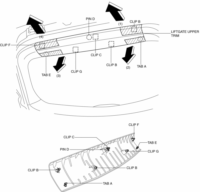
1. Take the shaded area shown in the figure, detach tab A while pulling the liftgate upper trim in the direction of the arrow (1) shown in the figure, then detach clips B, clip C and pin D while pulling in the direction of the arrow (2).

2. Take the shaded area shown in the figure, detach tab E while pulling the liftgate upper trim in the direction of the arrow (3) shown in the figure, then detach the clip F, clip G while pulling in the direction of the arrow (4).
3. Install in the reverse order of removal.
 Liftgate Side Trim Removal/Installation
1. Remove the liftgate upper trim..
2. Remove the fastener A.
3. Take the shaded area shown in the figure, and pull the liftgate side trim
in the direction of the arrow (1) while detaching clips ...
 Meter Hood Removal/Installation
1. Disconnect the negative battery cable..
2. Remove the upper column cover.
3. Using a phillips screwdriver, remove fasteners.
NOTE:
When pulling up the shaft of fasteners using a phill ...
Other materials:
Engine Coolant
Inspecting Coolant Level
WARNING
Do not use a match or live flame in the engine compartment. DO NOT ADD COOLANT
WHEN THE ENGINE IS HOT:
A hot engine is dangerous. If the engine has been running, parts of the engine
compartment can become very hot. You could be burned.
Carefully inspect the e ...
Ultra High Tension Steel [Construction]
Characteristics of Ultra High-Tensile Steel Plates
Ultra high-tensile steel plates have enhanced tensile strength compared to
previous high-tensile steel plates.
Because the strength is maintained even though the plates are thin-walled,
the ultra high-tensile steel plates ar ...
Compression Inspection
WARNING:
Hot engines and oil can cause severe burns. Be careful not to burn yourself
during removal/installation of each component.
Fuel vapor is hazardous. It can very easily ignite, causing serious injury
and damage. Always keep sparks and flames away from fuel.
Fuel ...
