
Mazda CX-5 Service & Repair Manual: Liftgate Adjustment
1. Measure the gap and height difference between the liftgate and the body.
2. Loosen the liftgate hinge installation bolts and adjust the liftgate.
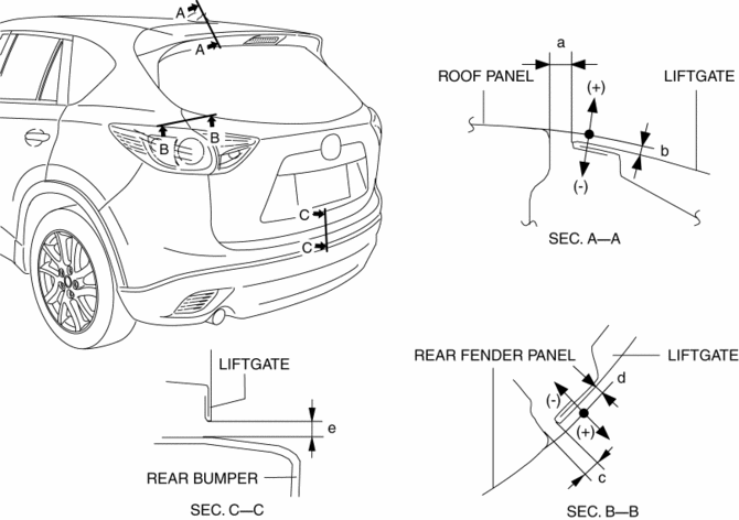
-
Standard clearance
-
a: 5.2?7.2 mm {0.21?0.28 in}
-
b: -2.0?0 mm {-0.078?0.000 in}
-
c: 3.8?6.2 mm {0.15?0.24 in}
-
d: -1.6?0.8 mm {-0.06?0.03 in}
-
e: 3.8?7.8 mm {0.15?0.30 in}
3. Tighten the liftgate hinge installation bolts..
4. If the liftgate does not open/close smoothly, adjust it by loosening the liftgate lock striker installation screw..
5. Spray or pour water on the door and surrounding area using a hose or high pressure water pressure car wash and verify that there is no water leakage.
 Hood Removal/Installation
WARNING:
Removing the hood without supporting it could cause the hood to fall and
cause serious injury. Always perform the procedure with at least another person
to prevent the hood from ...
 Liftgate Garnish Removal/Installation
1. Disconnect the negative battery cable..
2. Remove the following parts:
a. Liftgate upper trim.
b. Liftgate side trim.
c. Liftgate recess.
d. Liftgate lower trim.
3. Disconnect the conne ...
Other materials:
Supplemental Restraint System Components
1 Driver/Front passenger inflators and air bags
2 Roll-over sensorí, crash sensors, and diagnostic module (SAS unit)
3 Front seat belt pretensioners
4 Front air bag sensors
5 Side crash sensors
6 Air bag/front seat belt pretensioner system warning light
7 Side and curtain inflators ...
Wheel Hub Component Removal/Installation [Awd]
CAUTION:
Performing the following procedures without first removing the ABS wheel-speed
sensor may possibly cause an open circuit in the wiring harness if it is pulled
by mistake. Before performing the following procedures, disconnect the ABS wheel-speed
sensor connector (body side) ...
Compression Inspection
WARNING:
Hot engines and oil can cause severe burns. Be careful not to burn yourself
during removal/installation of each component.
Fuel vapor is hazardous. It can very easily ignite, causing serious injury
and damage. Always keep sparks and flames away from fuel.
Fuel ...
