Mazda CX-5 Service & Repair Manual: Lap Pre Tensioner Seat Belt [Two Step Deployment Control System]
Purpose
-
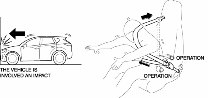
The lap pre-tensioner seat belts retract and tighten the seat belt webbing to protect the front passengers during a collision.
Function
-
The lap pre-tensioner seat belts operate (deploy) based on the operation signal from the SAS control module to instantly retract and tighten the belt webbing, restraining the driver.
-
The lap pre-tensioner seat belts operate in conjunction with the pre-tensioner seat belts.

Construction
-
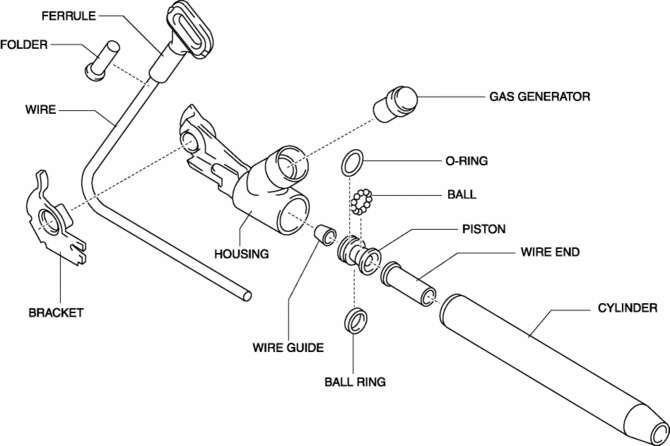
The lap pre-tensioner seat belts are installed to the anchors of the front seat belts.
-
The lap pre-tensioner seat belts consist of the following parts shown in the figure:

Operation
Lap pre-tensioner activation
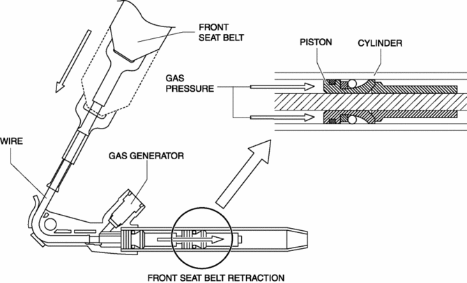
1. The gas generator emits a spark when a signal is received from the SAS control module, causing gas to form.
2. The gas pressure pushes the piston inside the tube, pulling the lead wire.
3. As the lead wire is pulled, the part of the seat belt attached to the wire is also pulled.
4. The slack in the belt is tightened by the front seat belt being pulled by the lap pre-tensioner seat belt and the seat belt ELR mechanism, restraining the passengers.

After activation
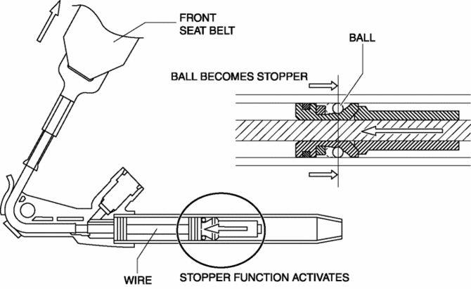
1. After operating (deploying) the pre-tensioner, the lead wire is pulled back. However the front seat belts are locked by activation of the stopper function so that the belt webbing is not released.
2. The restraint force of the seat belt is adjusted by the front seat belt load limiter mechanism, preventing injury to the driver and passenger from seat belt pressure.

Fail-safe
-
Function not equipped.
 Front Seat Belt Removal/Installation
WARNING:
Handling the front seat belt (pre-tensioner seat belt) improperly can accidentally
deploy the pre-tensioner seat belt, which may seriously injure you. Read the
air bag system se ...
 Pre Tensioner Seat Belt [Standard Deployment Control System]
Purpose
The pre-tensioner seat belt retracts and tightens the seat belt webbing to
protect the front passengers during a collision.
Function
The pre-tensioner seat belts operate ...
Other materials:
Front Seat Removal/Installation
WARNING:
Handling a side air bag improperly can accidentally operate (deploy) the
air bag, which may seriously injure you. Read the service warnings/cautions
in the Workshop Manual before handling the front seat (side air bag integrated)..
If the sliding mechanisms on both side ...
Fuel Pump Unit Disassembly/Assembly
WARNING:
Fuel is very flammable liquid. If fuel spills or leaks from the pressurized
fuel system, it will cause serious injury or death and facility breakage. Fuel
can also irritate skin and eyes. To prevent this, always complete the “Fuel
Line Safety Procedure”, while referring ...
Roof Molding Removal
1. Insert a tape-wrapped flathead screwdriver in the position shown in the figure.
2. Rotate a tape-wrapped flathead screwdriver in the direction of the arrow in
the order of (1), (2) shown in the figure and remove the roof molding from the front
T-stud.
3. Rotate the roof molding in th ...
