Mazda CX-5 Service & Repair Manual: Clock
Purpose
-
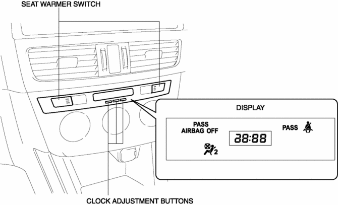
The clock displays the current time, the passenger and rear seat belt status, the passenger air bag deactivation (PAD) switch status, and the seat warmer operation status to notify the user.
Function
-
Stores the time set by the user and displays the current time.
Seat belt warning light function
-
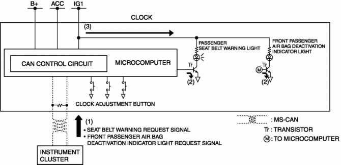
When the clock receives a seat belt warning light request signal sent via CAN transmission from the instrument cluster, it illuminates the seat belt warning light.
Front passenger air bag deactivation indicator light function
-
When the clock receives a front passenger air bag deactivation indicator light request signal sent via a CAN signal from the instrument cluster, it illuminates the front passenger air bag deactivation indicator light.
Construction
-
Consists of the display which displays the current time and indicator/warning lights, the clock adjustment button, and the seat warmer switch (with seat warmer).
-
Assembled to the climate control unit.
Operation
-
The clock displays the current time when the ignition is switched to ACC or ON (engine off or on).
Warning/indicator light operation
-
The clock receives (1) a seat belt warning request signal and front passenger air bag deactivation indicator light request signal from the instrument cluster.
-
The clock microcomputer turns the transistor on (2) based on each signal.
-
When the transistor turns on, a ground circuit with each warning/indicator light is established, and the warning/indicator light illuminates (3).
Seat warmer switch
-
For details on the seat warmer switch operation, refer to SEAT WARMER SYSTEM.
Fail-safe
-
Function not equipped.
 Active Command Modes Inspection [Instrument Cluster]
1. Connect the M-MDS to the DLC-2.
2. After the vehicle is identified, select the following items from the initialization
screen of the M-MDS.
a. Select “DataLogger”.
b. Select “Modulesâ ...
 Clock Input/Output Check Mode
Activation procedure
Inspection
NOTE:
The clock input/output check mode is displayed in the following order and
returning to the previous screen is impossible.
If you want to ...
Other materials:
Suspension Features
Improved rigidity and handling stability
A strut type front suspension adopted
E-type multi-link rear suspension adopted
For the front/rear crossmembers, the welded flange has been eliminated
(flange-less), the cross-section expa ...
Electric Variable Valve Timing Actuator, Hydraulic Variable Valve Timing Actuator
Removal/Installation
WARNING:
A hot engine can cause severe burns. Turn off the engine and wait until it
is cool before servicing.
CAUTION:
Do not disassemble the electric variable valve timing actuator and hydraulic
variable valve timing actuator because they are precision units.
If ...
Clock Spring Inspection [Two Step Deployment Control System]
1. Disconnect the negative battery cable and wait for 1 min or more..
2. Remove the driver?side air bag module..
3. Remove the steering wheel..
4. Remove the column cover..
5. Remove the clock spring..
6. Verify that the continuity is as indicated in the table.
If not as indicated ...
