Mazda CX-5 Service & Repair Manual: Center Roof Antenna Inspection
NOTE:
-
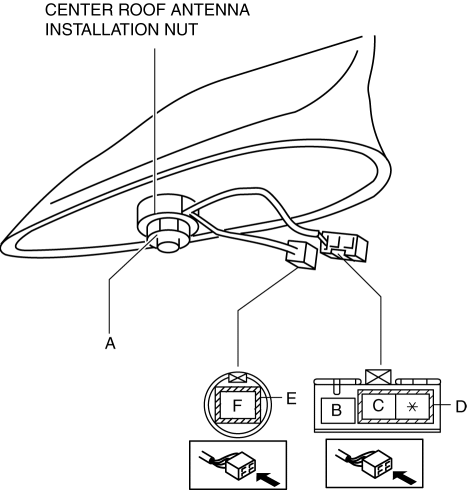
The center roof antenna is integrated with the antenna amplifier.
Antenna amplifier inspection
1. Disconnect the negative battery cable..
2. Remove the following parts:
a. Front scuff plate.
b. Rear scuff plate.
c. B-pillar lower trim.
d. Front seat belt adjusting cover.
e. Front seat belt upper anchor installation bolt.
f. B-pillar upper trim.
g. Trunk board.
h. Trunk end trim.
i. Trunk side trim.
j. D-pillar trim.
k. C-pillar trim.
3. Remove the rear passenger's assist handle..
4. Partially peel back the headliner.
NOTE:
-
Be careful not to peel back the headliner excessively. Otherwise it could create a fold-seam in the headliner.
5. Connect the negative battery cable..
6. Switch the ignition ON (engine off).
7. Turn the audio unit power on.
8. Tune in the radio.
9. Verify that the battery voltage is supplied to antenna amplifier terminal A.
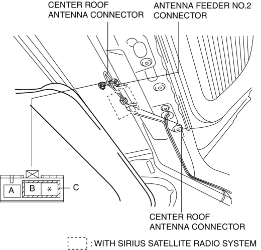
-
If the battery voltage cannot be verified, inspect the audio unit and antenna feeder.
-
If the battery voltage can be verified, go to the feeder line inspection.
Feeder line inspection
1. Disconnect the negative battery cable..
2. Remove the center roof antenna.
3. Verify that there is no continuity between center roof antenna sections A and B and E (with AM/FM/SIRIUS type only)
AM/FM type
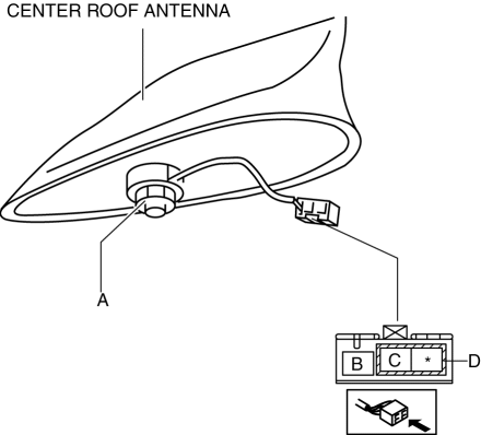
AM/FM/SIRIUS type
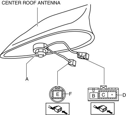
-
If there is continuity, replace the center roof antenna.
4. Install the center roof antenna.
5. Verify that the continuity between the center roof antenna terminals is as indicated in the table.
AM/FM type
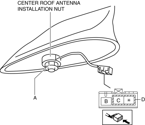
AM/FM/SIRIUS type
-
If the continuity is not as indicated in the table, verify the installation condition of the center roof antenna installation nut.
AM/FM type

AM/FM/SIRIUS type

-
If the installation condition of the center roof antenna installation nut is normal, replace the center roof antenna.
 Center Roof Antenna
Purpose, Function
Converts radio broadcast waves to electric signals and sends the signals
to the audio unit.
Construction
A center roof antenna has been adopted which does not ...
 Center Roof Antenna Removal/Installation
1. Disconnect the negative battery cable..
2. Remove the following parts:
a. Front scuff plate.
b. Rear scuff plate.
c. B-pillar lower trim.
d. Front seat belt adjusting cover.
e. Front se ...
Other materials:
Generator Inspection [Skyactiv G 2.0]
CAUTION:
Do not apply direct battery positive voltage to generator terminal D, otherwise
it could cause damage to the internal parts (power transistor) of the generator.
Charging system warning Light
1. Verify that the battery is fully charged.
2. Verify that the assembly conditi ...
Instrument Cluster Disassembly/Assembly
CAUTION:
If the instrument cluster is hit forcefully during disassembly such as by
being dropped, it could get damaged and the system may not operate normally.
When disassembling the instrument cluster, perform the procedure on a workbench
on clean clothes being careful not to drop ...
Electric Variable Valve Timing Motor/Driver Removal/Installation
WARNING:
A hot engine can cause severe burns. Turn off the engine and wait until it
is cool before servicing.
CAUTION:
Applying excessive force (force of 100 N {10.2 kgf, 22.5 lbf} or more) to
the electric variable valve timing motor/driver may cause a malfunction. When
...
