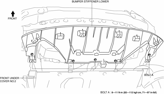
Mazda CX-5 Service & Repair Manual: Bumper Stiffener Lower Removal/Installation
1. Disconnect the negative battery cable..
2. Remove the following parts:
a. Seal board upper.
b. Front bumper.
c. Seal plate.
d. Front under cover No.1.
3. Remove bolts A.
4. Pull the bumper stiffener lower in the direction of the arrow (1), (2) shown in the figure, detach hooks B.
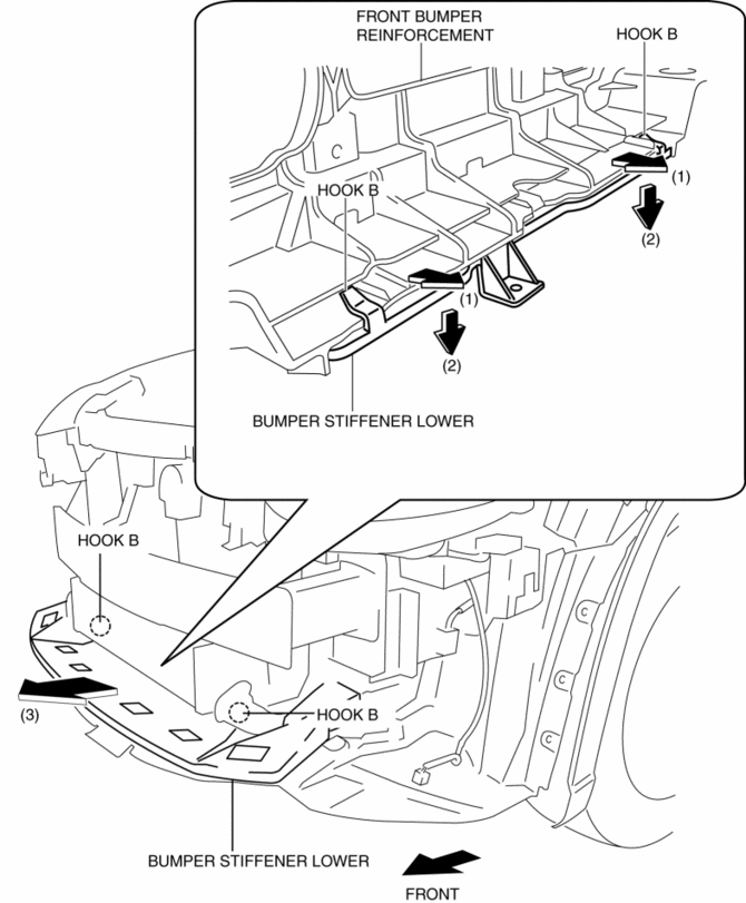
5. Remove the bumper stiffener lower in the direction of the arrow (3) shown in the figure.
6. Install in the reverse order of removal.
 Bumper Slider Removal/Installation
Front Bumper Slider
1. Disconnect the negative battery cable..
2. Remove the seal board upper..
3. Remove the front bumper..
4. Remove bolts A.
5. Pull the front bumper slider in the dire ...
 Center Under Cover Removal/Installation
1. Lift up the vehicle.
2. Remove the floor under cover..
3. Remove bolts.
2WD
AWD
4. Remove the center under cover.
5. Install in the reverse order of removal. ...
Other materials:
Exhaust System
Purpose, Outline
A 4-2-1 exhaust system has been adopted which reduces residual gas in the
cylinders using the scavenging effect and contributes to a high compression
ratio.
The loop structure of the exhaust pipes for the 4-2-1 system takes up less
space.
Structural Vie ...
A/C Compressor
Purpose
The A/C compressor circulates the refrigerant in the refrigerant cycle.
The A/C compressor compresses the gaseous refrigerant atomized by the evaporator,
and by pressurizing the gaseous refrigerant, liquification by the condenser
is facilitated.
Function
The ...
Clock Spring Inspection [Two Step Deployment Control System]
1. Disconnect the negative battery cable and wait for 1 min or more..
2. Remove the driver?side air bag module..
3. Remove the steering wheel..
4. Remove the column cover..
5. Remove the clock spring..
6. Verify that the continuity is as indicated in the table.
If not as indicated ...
