Mazda CX-5 Service & Repair Manual: Bumper Bracket Removal [Panel Replacement]
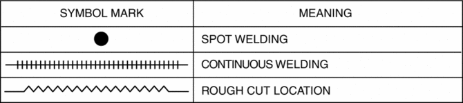
Symbol Mark
Removal Procedure
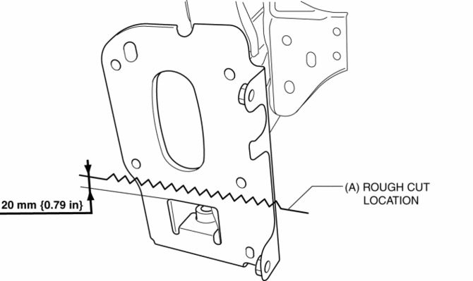
1. Rough cut area locations indicated by (A).
2. Grind the 6 locations indicated by (B) shown in the figure.
CAUTION:
-
When grinding 6 locations indicated by (B) shown in the figure and the front side frame is damaged, there is a possibility that attachment of a bracket may become difficulty. When grinding 6 locations indicated by (B) shown in the figure, the amount removed will affect the quality of the installation.
3. Grind the 2 locations indicated by (C) shown in the figure.
4. Drill the 2 locations indicated by (D) shown in the figure, then remove the half portion above the bumper bracket.
5. Drill the 3 locations indicated by (E) shown in the figure.
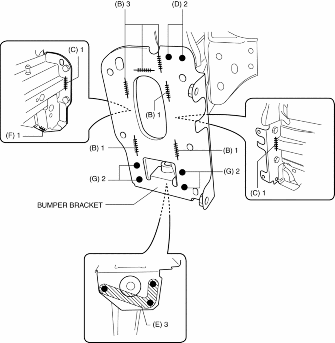
6. Grind the 1 location indicated by (F) shown in the figure.
7. Drill the 4 locations indicated by (G) shown in the figure.
8. Remove the half portion below the bumper bracket.
 Bumper Bracket Installation [Panel Replacement]
Symbol Mark
Installation Procedure
1. When installing new parts, measure and adjust the body as necessary to conform
with standard dimensions.
2. Drill holes for the plug welding 6 locations ...
 Bumper Slider Removal/Installation
Front Bumper Slider
1. Disconnect the negative battery cable..
2. Remove the seal board upper..
3. Remove the front bumper..
4. Remove bolts A.
5. Pull the front bumper slider in the dire ...
Other materials:
DSC Control
Outline
While a vehicle normally turns safely in response to steering operation,
there are instances when the limits of tire lateral grip is surpassed due to
road surface conditions or vehicle speed, and the influence of evasive steering
to avoid an accident or similar situations.
...
Turn Signal/Hazard Warning Indicator Lights
Purpose
Notifies the driver that a turn light, the hazard warning lights are flashing.
Function
Flashes according to the turn switch and hazard warning switch operations.
Construction
Displayed in the instrument cluster.
Operation
Turn system
1. When th ...
Rear Upper Arm Removal/Installation [2 Wd]
WARNING:
Verify that the crossmember is securely supported by a jack. If the rear
crossmember falls off, it can cause serious injury or death, and damage to the
vehicle.
CAUTION:
Performing the following procedures without first removing the rear ABS wheel-speed
...
