Mazda CX-5 Service & Repair Manual: Brake Fluid Pressure Sensor Inspection
1. Switch the ignition to off.
2. Remove the clips.
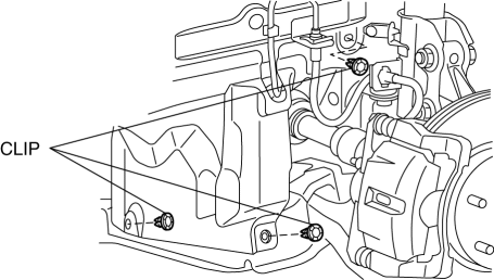
3. Set the splash shield out of the way.
4. Disconnect the brake pipe from the LF brake hose.
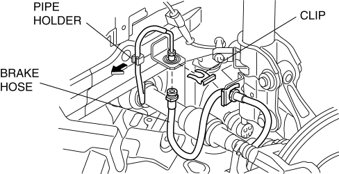
5. Remove the clip.
6. Remove the LF brake hose from the bracket.
7. Detach the brake pipe from the pipe holder.
8. Install the SST
to the brake pipe as shown in the figure.
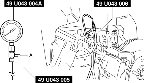
9. Bleed the brake line and the SSTs
of air. Bleed the air form the SSTs
using bleeder screw A.
10. Connect the M-MDS to the DLC-2.
11. Select the “BRK_F_P_R” PID.
12. Start the engine.
13. Depress the brake pedal, and confirm that the fluid pressure value of the SST
(Gauge) and the value shown on the M-MDS are equal
-
If the fluid pressures are different, replace the DSC HU/CM..
14. After the inspection, remove the SSTs
, install the brake hose, clamp, and brake pipe to the original positions, and then bleed the air from the brake line..
 Brake Fluid Pressure Sensor
Purpose/Function
The brake fluid pressure sensor detects the fluid pressure from the master
cylinder and transmits it to the DSC HU/CM.
Construction
The brake fluid pressure sen ...
 Pressure Sensor Removal/Installation [Two Step Deployment Control System]
WARNING:
Handling the pressure sensor improperly can accidentally operate (deploy)
the air bag module, which may seriously injure you. Read the air bag system
service warnings and cautio ...
Other materials:
Not P Position Switch Inspection
NOTE:
The not P position switch is built into the selector lever component.
1. Disconnect the negative battery cable..
2. Remove the front console..
3. Disconnect the selector lever component connector.
4. Verify that the continuity between selector lever component terminals ...
Front Console Box Removal/Installation
NOTE:
Affix protective tape to the position shown in the figure.
1. Insert a tape-wrapped flathead screwdriver in the position indicated by the
arrow in the figure and detach clips A.
2. Pull the front console box in the direction of the arrow (2) and remove it
while d ...
Washer Fluid Level Sensor
Purpose
The washer fluid-level sensor illuminates the low washer fluid level warning
light when the washer fluid level is lowered.
Function
The washer fluid-level sensor detects the decrease in the washer fluid level.
Construction
The washer fluid-level sensor con ...
