Mazda CX-5 Service & Repair Manual: Seat Belt Warning Alarm
Purpose
-
The seat belt warning alarm warns occupants that a seat belt is not fastened.
Function
-
The instrument cluster sounds the seat belt warning alarm based on the following CAN signals:
-
Vehicle speed signal sent from PCM
-
Driver/passenger buckle switch signal, occupancy sensor signal sent from SAS control module
Driver/passenger seat belt warning alarm sound function
-
The driver/passenger seat belt warning alarm has a warning for when the vehicle is stopped, while the vehicle is being driven, and subsequent warnings while the vehicle is being driven.
-
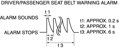
When all of the following conditions have been met, the alarm sounds.
-
Ignition switch ON (engine off or on)
-
Driver/passenger buckle switch on signal (seat belt unfastened) is detected
-
Occupancy sensor on signal (occupant in passenger seat) is detected (passenger seat belt warning alarm only)
-
The driver/passenger seat belt warning alarm sound pattern is as shown in the figure.

-
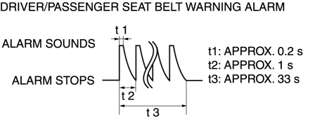
When all of the following conditions are met, the alarm sounds.
-
Vehicle speed is approx. 20 km/h {12 mph} or more
-
Driver/passenger buckle switch on signal (seat belt unfastened) is detected
-
Occupancy sensor on signal (occupant in passenger seat) is detected (passenger seat belt warning alarm only)
-
The driver/passenger seat belt warning alarm sound pattern is as shown in the figure.

-
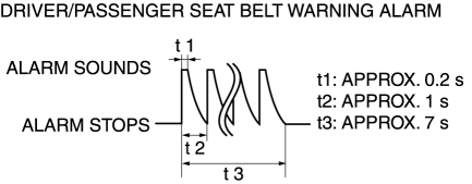
When all of the following conditions are met, the alarm sounds.
-
Vehicle speed is approx. 20 km/h {12 mph} or more
-
Occupancy sensor on signal (occupant in passenger seat) is detected (passenger seat belt warning alarm only)
-
After initial warning operates, buckle switch off signal (seat belt fastened) to on signal (seat belt unfastened) is detected
-
The driver/passenger seat belt warning alarm sound pattern is as shown in the figure.

-
Warning while vehicle is stopped
-
Warning while vehicle is being driven
-
Subsequent warning
Construction
-
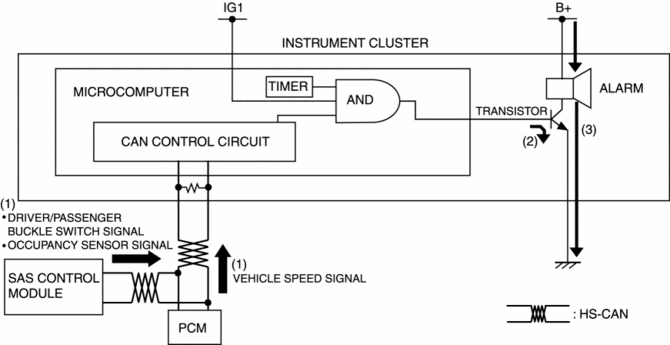
The seat belt warning alarm sounds using the buzzer built into the instrument cluster.
Operation
1. The instrument cluster receives (1) the vehicle speed signal from the PCM, the driver/passenger buckle switch signal and occupancy sensor signal from the SAS control module when the ignition is switched ON (engine off or on).
2. The instrument cluster microcomputer turns the transistor on (2) based on each signal.
3. When the transistor turns on, a ground circuit with the alarm is established and the alarm sounds (3).

Fail-safe
-
Function not equipped.
 Power Steering Malfunction Indicator Light
Purpose
The power steering malfunction indicator light warns the driver that there
is a malfunction with the electric power steering (EPS) system.
Function
If there is a malfunc ...
 Seat Belt Warning Light
Purpose
The seat belt warning light warns the driver that a seat belt is not fastened.
Function
The instrument cluster flashes/illuminates the seat belt warning light based
on t ...
Other materials:
Ion Sensor
Purpose/Function
Detects ion generation in the combustion chamber for detecting pre-ignition.
Detects ions which occur due to fuel combustion as current by applying bias
voltage to the spark plug, which is amplified in the ignition coil internal
circuit and input to the PCM.
...
Side Air Bag Sensor Removal/Installation [Two Step Deployment Control System]
WARNING:
Handling the side air bag sensor improperly can accidentally operate (deploy)
the air bag module, which may seriously injure you. Read the air bag system
service warnings and cautions before handling the side air bag sensor..
1. Switch the ignition to off.
2. Disconnec ...
Cooling System
Outline
Passing water resistance is reduced by improvement of the engine coolant
passage shape.
Pump efficiency is improved by changing the water pump impeller to the closed
impeller.
Structural View
Flow Chart
Structure
Consists of the followi ...
